Service Manual version 1008
OP 1200/1500/1700 (PC920 Intel 945G)
4-29
4.1.2. Knocking down the panel PC’s Individual Modules
The panel PC is now separated into several individual modules. You may need to further knock some
modules down into parts for repair purpose. Refer to the following sections to detach the components
from these modules.
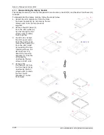
4.1.2.1. Disassembling the PC I/O Module
The I/O module is mainly composed of three I/O boards. All the onboard I/O signal of the OP SERIES’s
motherboard is connected to these boards for external device connection.
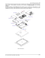
1. Detach the I/O board module (1) from the PC I/O cover (2) by unscrewing the four retaining
screws.
2. Detach the 22P*2 flat cable used to link the IO-005 (3) and IO-006 (4) boards.
3. Detach the two IO boards from the I/O bracket (5) by loosening the securing bolts and retaining
screw.
4. Remove the external IDE board (6) from the PC I/O cover by loosening the four retaining screws.
5. Detach the filter cover (7) from the PC I/O cover by unscrewing the four retaining screws.
(2)
(1)
(3)
(4)
(5)
(7)
(6)
Summary of Contents for OP 1200
Page 8: ......
Page 32: ...Service Manual version 1008 OP 1200 1500 1700 PC920 Intel 945G 4 24...
Page 79: ...Service Manual version 1008 OP 1200 1500 1700 PC920 Intel 945G 6 71...
Page 91: ...Service Manual version 1008 OP 1200 1500 1700 PC920 Intel 945G 7 83...
Page 106: ...Service Manual version 1008 OP 1200 1500 1700 PC920 Intel 945G 7 98...
Page 109: ...Service Manual version 1008 OP 1200 1500 1700 PC920 Intel 945G 7 101...
Page 112: ...Service Manual version 1008 OP 1200 1500 1700 PC920 Intel 945G 7 104...

