Service Manual version 1008
OP 1200/1500/1700 (PC920 Intel 945G)
6-60
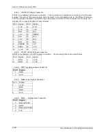
6.1.6.1. ATXP1: ATX Power Connector
ATXP1 is a standard ATX power connector. This connector is provided to connect to an ATX power
supply. The plug of the power supply will only insert in one orientation due to the different hole size.
Find the proper orientation and push down the power connector firmly to make sure the pins are
aligned. Its pin assignments are listed below
:
Pin # Signal
Pin #
Signal
3.3V
11
3.3V
2
3.3V
12
-12V
3
Gnd
13
Gnd
4
+5V
14
PSON#
5
Gnd
15
Gnd
6
+5V
16
Gnd
7
Gnd
17
Gnd
8
PWROK 18
-5V
9
SB5V
19
+5V
10
+12V
20
+5V
6.1.6.2. ATXP2: ATX +12V Power Connector
ATXP2 is a st12V ATX power connector. Its pin assignments are listed below
Pin # Signal
Pin #
Signal
1
GND
3
+12V
2
GND
4
+12V
6.1.6.3. CN1: Touchscreen Power Connector
Pin # Signal
1
GND
2
VCC
6.1.6.4. PWR1: Power Output Connector
Pin #
Signal
1
+12V
GND
GND
2
VCC
6.1.6.5. INV1:
LCD Inverter Connector
Pin # Signal
1
Backlight ADJ
2
GND
3
Backlight Enable
4
12V
Summary of Contents for OP 1200
Page 8: ......
Page 32: ...Service Manual version 1008 OP 1200 1500 1700 PC920 Intel 945G 4 24...
Page 79: ...Service Manual version 1008 OP 1200 1500 1700 PC920 Intel 945G 6 71...
Page 91: ...Service Manual version 1008 OP 1200 1500 1700 PC920 Intel 945G 7 83...
Page 106: ...Service Manual version 1008 OP 1200 1500 1700 PC920 Intel 945G 7 98...
Page 109: ...Service Manual version 1008 OP 1200 1500 1700 PC920 Intel 945G 7 101...
Page 112: ...Service Manual version 1008 OP 1200 1500 1700 PC920 Intel 945G 7 104...


