Service Manual version 1008
OP 1200/1500/1700 (PC920 Intel 945G)
4-26
4.1. What Contains in each Module
The OP SERIES panel PC is mainly composed of two parts, one front bezel module and the other
panel PC module. Under some conditions, you might need to knock down the system into parts to
access some internal components for specific purpose. Most of the devices in the systems are
integrated to devices brackets, then install to the system. If you are removing the devices out of
the cabinet or the PC compartment for testing purpose, please keep the devices on their brackets
as they were. If the devices are to be sent back to the manufacturer for repair, please remove
them from the brackets and send back the devices only.
This chapter highlights the steps to knock down the system into parts. Please be reminded again that
only trained technicians are allowed to open the system for maintenance and service
. You might not
need to knock the system completely into individual parts to find the needed components.
Disassembling the Panel PC
The following table lists the hierarchy of each individual in the panel PC.
LEVEL
DECRIPTION
0.1
Panel PC
..2
Display Module
...3
Front Bezel Module
...3
LCD Module
..2
PC Module
...3
Motherboard Module
...3
HDD Module
...3
Touchscreen Controller Module
...3
Expansion Door Module
...3
Inverter Module
...3
Slim CD-ROM/FDD Module
...3
Power Supply Module
...3
Riser Card Module
...3
PC I/O Cover Module
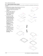
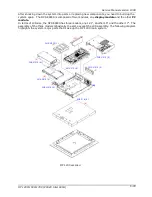
The following steps highlight the procedures to knock the panel PC into individual modules.
1. Remove the metal PC I/O cover by loosening the seven retaining screws.
2. Unplug the IDE cable on the external IDE board.
3. Remove the riser card module from the motherboard’s ESIA slot.
4. Disconnect the two power supply’s power cables and the power switch cable from the
motherboard. Disconnect the two 4-pole power cables from the HDD and CD-ROM. Remove the
power supply module from the chassis by unscrewing the four retaining screws.
5. Unplug all the cables on the motherboard coming from the CD-ROM/FDD module. Detach the
CD-ROM/FDD module by removing the three retaining screws.
6. For OP 1500 and 170, disconnect the inverter cable. Remove the inverter cover by loosening the
two retaining screws. Disconnect the two LCD power wires from the inverter. Remove the inverter
by loosening the two retaining bolts.
7. Disconnect the LVDS cable and the two touchscreen cables and power wire from the motherboard.
Detach the chassis from the display module by loosening the six retaining screws.
8. Detach the expansion door from the chassis by loosening the three retaining screws.
9. Detach the touchscreen controller module from the chassis by loosening the two retaining screws.
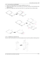
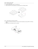
10. Detach the IDE cable of the HDD module from the motherboard. Remove the HDD module from
the chassis by loosening the retaining screw.
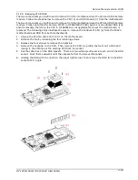
11. Remove the motherboard from the chassis by unscrewing the eight retaining screws.
Summary of Contents for OP 1200
Page 8: ......
Page 32: ...Service Manual version 1008 OP 1200 1500 1700 PC920 Intel 945G 4 24...
Page 79: ...Service Manual version 1008 OP 1200 1500 1700 PC920 Intel 945G 6 71...
Page 91: ...Service Manual version 1008 OP 1200 1500 1700 PC920 Intel 945G 7 83...
Page 106: ...Service Manual version 1008 OP 1200 1500 1700 PC920 Intel 945G 7 98...
Page 109: ...Service Manual version 1008 OP 1200 1500 1700 PC920 Intel 945G 7 101...
Page 112: ...Service Manual version 1008 OP 1200 1500 1700 PC920 Intel 945G 7 104...

