Service Manual version 1008
OP 1200/1500/1700 (PC920 Intel 945G)
7-82
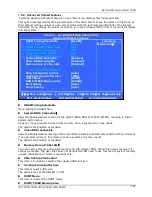
Primary HDDs/Secondary HDDs
This field is used to configure the IDE hard drive installed in the system. Move the cursor to highlight
the IDE Primary/Secondary Master/Slave fields and press <Enter>. The IDE Primary Master submenu
opens
:
IDE HDD Auto-Detection
Press <
Enter
> while this item is highlighted if you want the Setup Utility to automatically detect and
configure a hard disk drive on the IDE channel.
IDE Primary/Secondary Master/Slave
If you leave this item at Auto, the system will automatically detect and configure any IDE devices it
finds. If it fails to find a hard disk, change the value to Manual and then manually configure the drive
by entering the characteristics of the drive in the fields described below
:
Capacity
– displays the capacity of the HDD in megabytes (MB).
Cylinder
– indicates the number of cylinders that the HDD has. A cylinder is the sum total
of all tracks that are in the same location on every disk surface.
Head
– displays the number of heads in the HDD. A head is a device that reads and writes
data on the hard disk.
Precomp
– displays the track where precompensation is initiated. Precompensation is a
feature whereby the HDD uses a stronger magnetic field to write data in sectors that are
closer to the center of the disk. In CAV recording, in which the disk spins at a constant speed,
the sectors closest to the spindle are packed tighter than the outer sectors.
Landing Zone
– displays the location of the safe non-data area on a hard disk that is used
for parking the read/write head.
Sector
– displays the number of sectors available on the HDD. A sector is the smallest unit
of storage space on a disk.
If no hard disk is installed, select NONE and press <Enter>.
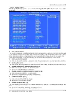
Drive A type/Drive B type
The item identifies the types of floppy disk drive A or drive B that has been installed in the computer.
None
No floppy drive installed
360K, 5.25"
5.25 inch PC-type standard drive; 360K byte
1.2M, 5.25"
5.25 inch AT-type high-density drive; 1.2M
bytes (3.5 inch when 3 Mode is Enabled).
720K, 3.5"
3.5 inch double-sided drive; 720K byte
1.44M, 3.5"
3.5 inch double-sided drive; 1.44M byte
2.88M, 3.5"
3.5 inch double-sided drive; 2.88M byte
Video
This item defines the video mode of the system. This main board has a built-in VGA graphics system;
you must leave this item at the default setting.
Halt on
This item defines the operation of the system POST (Power On Self Test) routine. You can use this
item to select which types of errors in the POST are sufficient to halt the system.
Panel Number
The item selects the panel resolution and LVDS interface for single or dual.
Base Memory, Extended Memory and Total Memory
These items are automatically detected by the system at start up time. These are display-only fields.
You cannot make changes to these fields.
Base Memory
– This field displays the amount of conventional memory detected by the
system during boot.
Extended Memory
– This field displays the amount of extended memory detected by the
system during boot.
Total Memory
– This field displays the total amount of memory (Base and Extended) detected by the system during
boot.
Summary of Contents for OP 1200
Page 8: ......
Page 32: ...Service Manual version 1008 OP 1200 1500 1700 PC920 Intel 945G 4 24...
Page 79: ...Service Manual version 1008 OP 1200 1500 1700 PC920 Intel 945G 6 71...
Page 91: ...Service Manual version 1008 OP 1200 1500 1700 PC920 Intel 945G 7 83...
Page 106: ...Service Manual version 1008 OP 1200 1500 1700 PC920 Intel 945G 7 98...
Page 109: ...Service Manual version 1008 OP 1200 1500 1700 PC920 Intel 945G 7 101...
Page 112: ...Service Manual version 1008 OP 1200 1500 1700 PC920 Intel 945G 7 104...


