Service Manual version 1008
OP 1200/1500/1700 (PC920 Intel 945G)
5-44
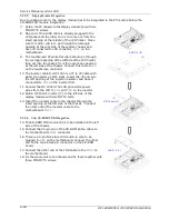
5.2.2. Touchscreen Controller Assembly
For easy maintenance in the future, the touchscreen controller is to be installed to a bracket rather
than to the system compartment directly.
1. For Elo touch, the touchscreen cable (3) is a flat cable with 5P*2 box headers at both sides. One
end is connected to
P3
on the touchscreen controller (1) first.
2. There is a 2P (black & red) power wire (4) to provide the power source for the touchscreen.
Connect one end to
P2
on the controller.
3. Make the controller’s coach chip (5) at the upper side. Retain the touchscreen controller to the
bracket (2) with two PMS M3*5 screws.
`
5.2.3. HDD Module Assembly
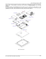
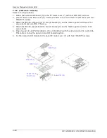
The panel PC is able to accommodate a 3.5” HDD. It is to be integrated to the drive bay first, then to
the chassis.
1. Retain the hard disk drive (1) to the HDD bay (2) with four FMS 6#32 5L screw at each side.
2. Connect one end of a 20P*2 HDD ribbon cable to the hard disk.
HDD
INSTALLATION
(2)
(1)
FMS 6#32 5L (4)
(2)
(1)
PMS M3*5 (2)
(3)
(4)
(5)
Summary of Contents for OP 1200
Page 8: ......
Page 32: ...Service Manual version 1008 OP 1200 1500 1700 PC920 Intel 945G 4 24...
Page 79: ...Service Manual version 1008 OP 1200 1500 1700 PC920 Intel 945G 6 71...
Page 91: ...Service Manual version 1008 OP 1200 1500 1700 PC920 Intel 945G 7 83...
Page 106: ...Service Manual version 1008 OP 1200 1500 1700 PC920 Intel 945G 7 98...
Page 109: ...Service Manual version 1008 OP 1200 1500 1700 PC920 Intel 945G 7 101...
Page 112: ...Service Manual version 1008 OP 1200 1500 1700 PC920 Intel 945G 7 104...


