6 Programming Features
109
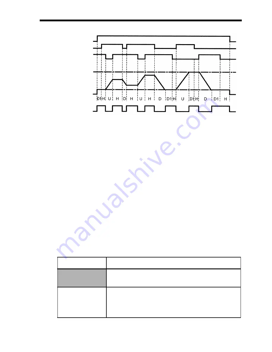
Time Chart for Up/Down Command Input
Note: 1. When Up/Down Commands are selected, the upper limit speed is set
regardless of frequency reference.
Upper limit speed = Maximum Output Frequency (n011)
×
Frequency Reference Upper Limit (n033)/100
2. Lower limit value is either the Minimum Output Frequency (n016) or
the Frequency Reference Lower Limit (n034) (whichever is larger.).
3. When the FWD (REV) Run Command is input, operation starts at the
lower limit speed without using the Up/Down Commands.
4. If the Jog Command is input while running for an Up/Down Com-
mand, the Jog Command has priority.
5. Multi-step speed references 1 to 4 are not effective when an Up/Down
Command is selected.
6. When 1 is set for the HOLD Output Frequency Memory Selection
(n100), the output frequency can be recorded during HOLD.
Setting
Description
0
Output frequency is not recorded during
HOLD.
1
When HOLD status is continued for 5 seconds
or longer, the output frequency during HOLD
is recorded and the Inverter restarts at the re-
corded frequency.
FWD Run
Up Command S6
Down Command S7
Upper Limit Speed
Lower Limit Speed
Output Frequency
Frequency Agree
Signal
U = Up (accelerating) status
D = Down (decelerating) status
H = Hold (constant speed) status
U1 = Up status, clamping at upper limit speed
D1 = Down status, clamping at lower limit speed


