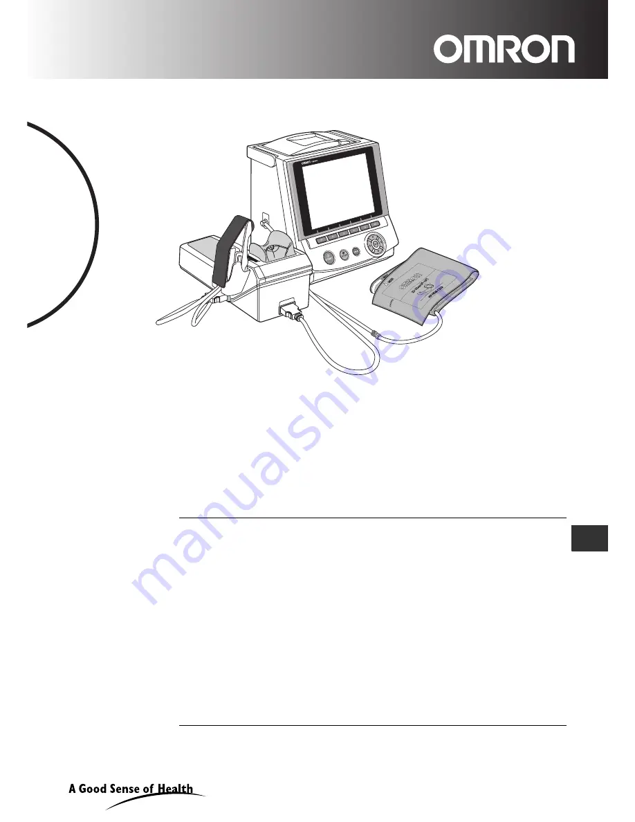
background image

HEM-9000AI

Non-Invasive

Blood Pressure Monitor 

with Augmentation


Index (AI)

• Instruction Manual
• Mode d’emploi
• Gebrauchsanweisung
• Manuale de instructone
• Manual de instrucciones
• Gebruiksaanwijzing

 XXXXXXXXXXXXXXXXXXXXXXXX

EN

IM-HEM9000-AI-E-01-07/06

Thank you for purchasing the OMRON HEM-9000AI unit.

Read all of the instructions in the instruction manual before you operate the unit 
and keep it near the unit all the times for future reference.

FR

DE

IT

ES

NL

CZ

Summary of Contents for HEM-9000AI

Page 1: ...nuale de instructone Manual de instrucciones Gebruiksaanwijzing XXXXXXXXXXXXXXXXXXXXXXXX EN IM HEM9000 AI E 01 07 06 Thank you for purchasing the OMRON HEM 9000AI unit Read all of the instructions in the instruction manual before you operate the unit and keep it near the unit all the times for future reference FR DE IT ES NL CZ ...

Page 2: ...ent Method and Registering ID Information 22 8 5 Loading Printer Paper 23 9 Measurement Preparation 24 9 1 How to Apply the Blood Pressure Cuff 24 9 2 How to Apply the AI Pulse Wave Sensor Unit 26 10 Post Measurement 29 10 1 How to Remove the AI Pulse Wave Sensor Unit 29 11 Selecting the Measurement Method 30 11 1 Selecting the Measurement Method 30 12 AI Blood Pressure Measurement 31 12 1 Measuri...

Page 3: ...ions 64 18 1 How to Change the Settings 64 18 2 How to Change the Setup 66 18 3 How to Change the Measurement Settings 67 18 4 How to Change Settings for Printing 70 18 5 How to Change Display Sound Settings 74 18 6 How to Change the Clock Settings 76 18 7 How to Change Settings for Storing 77 18 8 Returning to the Default Settings 78 18 9 Registering Hospital Name 79 18 10 Memory Card 80 18 11 Ke...

Page 4: ...raindications for use As with any non invasive measurement device there are clinical conditions which can influence the accuracy of the results Also the subject s position physiological condition and other environmental factors can affect the measurement calculation The OMRON HEM 9000AI Non Invasive Blood Pressure Monitor with Augmentation Index should not be used with patients who have the follow...

Page 5: ...e Notes on Safety or the operational method mentioned in this Instruction Manual 5 Under the circumstances not within the operating conditions of this unit including the power source or the setting environment mentioned in this Instruction Manual 6 The problem and damage caused by the result s of remodeling or improper repair of this product 7 The problem and damage caused by act of god such as fi...

Page 6: ...safe and correct use of the product and to prevent harm or damage to you and others Symbols and definitions are as follows Warning Indicates a possibility that people will suffer death or serious injury resulting from incorrect use Caution Indicates a possibility that people will be injured or objects will be damaged resulting from incorrect use ...

Page 7: ...n or pin receptacle If plugged into incorrect outlet electric shock might result Device Use Plug the main unit into an outlet do not plug into a multi plug outlet adapter Fire or electrical shock might result Plug the power cord in firmly Clean dust off on the power cord Electric shock a short circuit or fire might result Do not use when the power cord is damaged or not firmly plugged in Electric ...

Page 8: ...s for replacement of the fuses Do not connect the HEM 9000AI to commercial computers or devices that do not meet medical safety standards This could cause electric shock This device meets medical safety standards and the leakage current is limited to be within standard specifications Apply the pulse wave sensor on bare skin Pulse waves might not be detected and unnecessary pressure might be applie...

Page 9: ...vice upside down Electric parts and mechanical parts might break down Device Use Do not install parts or instruments not specified for this device Do not push the buttons or LCD display with any sharp or hard material Failure or damage might result Do not touch the AI pulse wave sensor with any sharp or hard material Damage might result Do not insert and remove the memory card while saving or retr...

Page 10: ...an inaccurate measurement result Apply the Blood Pressure Cuff properly Refer to Section 9 1 The device might display an inaccurate measurement result Device Maintenance Unplug the main unit connector from outlet when not in use for a long period Electric shock or an electric discharge fire due to deterioration of the insulating material might result Turn off and unplug the main connector when ins...

Page 11: ...urface of the wrist rest the outside of the AI pulse wave measurement unit the cuff and cables with the following procedure 1 Use a damp cloth with 30 to 50 isopropyl alcohol or 70 ethyl alcohol for cleaning the surface DO NOT use gasoline thinner benzene or highly concentrated alcohol when cleaning this device Do not disinfect this unit by autoclave or gas sterilization EOG formaldehyde or high c...

Page 12: ... cuff in 3 sizes S M and L with built in air bag See cuff size information in Section 6 ACCESSORIES Air Tube 1 3 m Model HEM 9T1 3 Art no 6984328 4 Connection Cable Model HEM 9000 CABLEZ Art no 9956251 4 Power Cord Model NEU12 2 Art no 1096522 0 Printer Paper 1 Roll Included Sold 5 rolls to a box Model HEM 9000 PAPERZ Art no 6970159 5 Memory Card to record measurements 128 MB Model HEM 9000 IC128Z...

Page 13: ...39 7 Applicable arm circumference 17 to 22 cm Air Tube 1 0 m Model HEM TUBE 100X Art no 6984327 6 Keyboard Model HEM 9000 KEYBZ Art no 9951049 2 Wheeled Cart with basket to place cuff Model HEM 9000 STANDZ Art no 7980234 9 Memory Card 128MB Model HEM 9000 IC128Z Art no 9956250 6 Printer Paper 5 Roll Set Model HEM 9000 PAPERZ Art no 6970159 5 Power Cord for U K Model HEM 9000 ACCAU Art no 9983975 3...

Page 14: ... as the pulse wave pattern In addition an incisura notch on the back of the reflected wave represents a pressure change caused by reverse flow as the aortic valve located at the opening of the aorta is closed Pulse Wave and Blood Pressure The pulse wave represents a local blood pressure change caused by the passage of blood from the left ventricle into the aorta accompanied by the wave action thro...

Page 15: ...ard slot G Eject button H Main unit I START button J STOP button K DISPLAY button L DISPLAY light M LCD display The material used in the front of the panel is PMMA N Function keys O Left right up down movement select buttons P SET button Q Power switch R Power connector S AI measurement unit connector T USB connectors 2 U Maintenance connector not used A D E I M N O P J K L Q R S T U B C F G H ...

Page 16: ...se line D Indicator lights E AI Pulse Wave sensor unit F AI Pulse Wave sensor unit connector G Air connector H Elbow placement board I AI Pulse Wave sensor unit storage clip J Rubber wrist rest K Main unit connector L Wrist belt M Fastener A E F G H B C I J L M K D C ...

Page 17: ... patient s left hand for measurement and on the patient s right side for right hand measurement 4 Plug one end of the connection cable see Section 5 for illustration into the main unit connector on the back of the AI pulse wave measurement unit The plug will click and lock into place Fig 3 5 Plug the other end of the connection cable into the AI measurement unit connector on the back of the main u...

Page 18: ... less than the total card memory Fig 6 8 Load the printer paper Refer to 8 5 Loading Printer Paper 9 Plug the female end of the power cord into the back of the main unit Then plug the male end of the power cord into an electrical outlet with grounding 10 Press the I end of the power switch at the back of the main unit Fig 7 After displaying Starting up Please wait for a moment for approximately 30...

Page 19: ... F5 SETUP appears at the bottom Fig 1 2 The setup screen will be displayed Move the cursor in the upper left part of the screen up or down using the buttons to select DATE TIME from the menu column Press the SET button or the button to move the cursor to the right Figs 2 and 3 Fig 1 Fig 2 Fig 3 ...

Page 20: ...the button to select the item day month year under SETTING VALUE to change Fig 5 Use the buttons to change the setting value These buttons increase and decrease the values for day month and year The year setting range is from 2005 to 2030 Press the SET button to accept the selected values The date format can be changed Refer to Section 18 6 Fig 5 Fig 4 ...

Page 21: ...VALUE to change Fig 7 Use the buttons to change the setting value These buttons increase and decrease the values for hour minute and second Press the SET button to accept the selected values The clock will resume as soon as the SET button is pressed To accurately set the clock to the correct time set it slightly in advance and press the SET button as soon as the set time becomes the current time P...

Page 22: ...suring AI the duration can be set to any of the following 15 seconds 30 seconds 1 minute or 3 minutes The measurement time set here is the duration of the pulse wave sampling The total time required for measurement is slightly longer The default setting is 30 seconds To change this setting follow the instructions in Section 18 3 2 Registering the patient s ID Register the patient s ID before begin...

Page 23: ...h the cover closed until it locks into place Fig 11 Fig 9 Fig 8 Load the printer paper as shown in the diagram Pull out the paper so that it protrudes from the printer cover when closing When loading a new roll of paper pull the end out about 25 cm 10 inches The end of the roll is sealed with glue which does not make a suitable printing surface Make sure you use OMRON printer paper refer to Sectio...

Page 24: ...to the main unit connect the air tube plug firmly into the air connector as shown in Fig 3 Connect the air tube and the cuff bladder set by turning as shown in Fig 4 A total air tube length of 1 5 m is provided with the Air Tube HEM 9T1 3 in the package Arm circumference Name of the arm cuff 17 22cm Small size adult arm cuff 22 32cm Medium size adult arm cuff 32 42cm Large size adult arm cuff IND ...

Page 25: ...NGE select a different more appropriate size cuff according to the circumference of the arm and wrap again If not wrapped with appropriate cuff the arm might become numb or the HEM 9000AI might not be able to measure blood pressure correctly Wrapping the cuff at an angle will have no impact on the measurements so allow the cuff to follow the shape of the arm 6 Align the cuff to be at the same heig...

Page 26: ...e of the wrist rest indicated by the thumb side printing on the wrist rest Figs 15 and 16 Align the wrinkle of the wrist joint with the wrist position mark on the wrist rest Fig 15 Instruct the patient saying relax your hand Patient s palm will face the front naturally It should be a little limp 2 Adjust the elbow placement board Adjust the elbow placement board of the AI pulse wave measurement un...

Page 27: ...n and is hard to the touch Once a point for taking a reading is located attach the AI pulse wave sensor unit snugly to the wrist allowing no gap to form between the unit and the wrist With the palm up take the reading from the artery next to the protrusion of the radius on the thumb side Fig 18 Even if the pulse is strong but the bone is not close to the skin the blood vessel may be hard to access...

Page 28: ...ner to hold the unit in place Figs 21 22 5 Confirm the artery s position again Confirm if the AI pulse wave sensor unit frame s black lines intersect the artery by palpation Figs 23 24 Instruct the patient to relax and not to move If misaligned go back to 4 above 6 Adjust the sensor Figs 25 and 26 Adjust the AI pulse wave sensor by pressing in the slide stoppers on both sides Continue moving the A...

Page 29: ...ments are complete Fig 27 Push down the slide stoppers on both sides and return the sensor to its original position Put the AI pulse wave sensor back in the storage clip 2 Remove the fastener from around the subject s wrist and store Fig 28 Attach the protection cap back on the sensor when it is stored Fig 28 Fig 27 ...

Page 30: ... option by pressing the F1 key MODE until the desired option is selected Figs 29 32 1 Measuring both AI and blood pressure Refer to Section 12 1 The AI and blood pressure can be measured either automatically alternating between the two measurements AI BP measurement or almost simultaneously using both arms AI BP simultaneous dual arm measurement Refer to Section 18 3 2 Measuring Blood Pressure Onl...

Page 31: ...he lower left part of the screen are both displayed 3 Press the START button to start measurement Fig 2 Inflation of the sensor unit will begin Inflation of the cuff will begin after AI pulse wave sensor pressure becomes stable If you wish to stop during measurement press the STOP button Deflation will occur rapidly When measurement takes more than 5 minutes the device will automatically stop Pres...

Page 32: ...n ascending descending or flat line see above When re measuring with an ascending or descending line it is possible to adjust the position of the AI pulse wave sensor by sliding it instead of having to remove and reattach the unit The artery is located in the direction of the LED lights that are lit While pressing in the slide stoppers adjust the pulse wave sensor by one or two scale units black l...

Page 33: ...ak in the graph of the AI values plotted for each pulse wave If the pulse is irregular or too faint the device may not detect the pulse wave in which case there will be no pulse waveform and nothing will be displayed on the graph A green bar in the lower left part of the screen shows the measurement progress toward completion 6 Once measurement is complete the results will appear along with a ligh...

Page 34: ...ure are simultaneously measured A blood pressure fluctuation is detected Measurement results may be compromised The BP value has been manually entered or edited cSBP is displayed only when AVG representative pulse wave is selected to display AI value and pulses for each pulse wave last 20 pulses Number of sampled pulse waves Pulse waveform Pulse wave number Histogram of AI value for each pulse wav...

Page 35: ...ement with the same ID will be displayed Select Yes or No Select the START button Yes to begin measurement Select the STOP button No to erase the ID and return to the default screen Enter the ID for the next patient Select the F1 key CANCEL to return to the previous screen and change the measurement mode Fig 9 Fig 8 Fig 9 Pulse wave number When the waveform is deformed or inflation is judged to be...

Page 36: ...ments displayed at the lower left corner of the screen see Fig 2 BP Single stands for a single BP measurement is the same as the number of measurements you selected in the case below the user selected a single measurement Make sure that the patient s name and ID are displayed at the upper left corner of the screen If they are not displayed enter or retrieve the patient s ID data according to the d...

Page 37: ...ent with the same ID will be displayed Select Yes or No Select the START button Yes to begin measurement Select the STOP button No to erase the ID and return to the default screen Enter the ID for the next patient Select the F1 key CANCEL to return to the previous screen and change the measurement mode Fig 7 Fig 5 Fig 6 Systolic blood pressure value Diastolic blood pressure value Pulse Pulse press...

Page 38: ...e measurement method display in the lower left part of the screen is set to MANUAL 3 Place the stethoscope on the patient s arm 4 Press the START button Inflation begins Fig 4 Do not press the START button without applying the cuff When you want to stop during measurement press the STOP button The cuff rapidly deflates Operator controlled Manual Inflation Holding the START button down during infla...

Page 39: ... Start measurement button If you wish to facilitate deflation after deflation has started press the F1 key DEFLATE It facilitates deflation by approximately 5 10 mmHg each time it is pressed 6 The strength of the pulse wave is displayed Pulse Wave Level with a bar during measurement Fig 6 7 Deflation continues until finished followed by a return to the initial screen Fig 7 Fig 5 Fig 6 Fig 7 ...

Page 40: ...ut first attaching the AI pulse wave sensor unit Do not slide the AI pulse wave sensor unit while AI measurement is in progress 3 Press the START button Fig 2 The AI pulse wave sensor unit will begin applying pressure To stop the device once measurement has begun press the STOP button Rapid deflation will occur If measurement takes more than five minutes the device will stop automatically Pressing...

Page 41: ...ard completion 6 Once measurement is complete the results will appear Fig 5 The green SAVING message will appear in the lower left part of the screen and the data will be recorded on the memory card Do not eject the memory card while save is in progress This could result in damage to the device 7 The beep to indicate that the data has been saved will sound and the dark blue message COMPLETE will a...

Page 42: ... START button Yes to begin measurement with the current ID Select the STOP button No to erase the ID and return to the default screen Enter the ID for the next patient Select the F1 key CANCEL to return to the previous screen and change the measurement mode Fig 9 Fig 8 Fig 9 Pulse wave number If during measurement the waveform becomes irregular or it is determined that the pressurization value is ...

Page 43: ...from among four options Once magnification is changed subsequent data will be displayed with the new magnification Changing Scroll Speed during AI Measurement The default continuous pulse wave scroll speed is 12 5 mm sec Press the button to change the scroll speed The setting can be switched from among two options When changing scroll speed subsequent data will be displayed with the new scroll spe...

Page 44: ...ter completing a measurement press the F6 key PRINT while the screen displays the measurement results Fig 1 To retrieve data from memory press the F4 key DATABASE and use the buttons to select the data to print After pressing the SET button to display the measurement results press the F6 key PRINT to print Refer to Section 16 The paper will automatically be fed and cut Storing Printed Results If t...

Page 45: ...BP value is left blank Example Print Single blood pressure measurement results Fig 4 Fig 3 Graph of average AI by age Upper Females Lower Males Note If the patient s gender has been entered only the appropriate line will be displayed Note The dotted line shows the standard deviation Note If the patient s birth date has not been entered the patient s data will not be plotted Note If the data to be ...

Page 46: ...nt screens or the measurement result screen 2 The latest 5 data items are displayed The total amount of data and the current data number are displayed on the lower left of the screen Use the keys to scroll up or down among individual data entries Use the keys to scroll through data in blocks of five entries at a time Align the cursor with the data to be retrieved and press the SET button to show d...

Page 47: ...nd graphs F5 key EDIT BP Enter the BP value edit screen F6 key DELETE DATA Delete data from database SET button Data Detail Display the Details screen STOP button CANCEL Return to the default screen To move the cursor up newer data use the button To move the cursor down older data use the button To move to the next page older data press the button To return to the previous page newer data press th...

Page 48: ...d at the lower left hand corner of the screen 3 PATIENT DATA Up to seven measurement results for a patient who has the specified ID will be displayed per page Fig 5 PATIENT DATA is sorted in the ascending order of the measurement date Use the keys to scroll up or down among individual data entries Use the keys to scroll through data in blocks of seven entries at a time Align the cursor with the da...

Page 49: ...ig 6 The total number of data entries and the current data number are displayed below the data list Use the keys to scroll up or down among individual data entries Use the keys to scroll through data in blocks of five or seven entries at a time 2 Press the F6 key DELETE DATA Fig 7 Fig 6 Fig 7 F1 key CANCEL Cancel deleting F3 key DELETE Delete the selected data entry STOP button CANCEL Cancel delet...

Page 50: ...is will be displayed only if pulse wave data is stored 3 Press the F1 key EXIT to return to the initial screen Pressing the other function keys results in the actions listed above DATA BASE ALL DATA screen Fig 8 F1 key EXIT Return to the pre measurement screen F2 key DATA LIST Enter the Data List screen F3 key EDIT REPLACE ID Edit or replace the ID information Refer to Section 17 2 for Edit and Se...

Page 51: ...f pulse wave data is stored Refer to Section 18 7 1 Press the F6 key on the DATA DETAIL screen Fig 10 At this time Select print contents will be displayed Fig 11 2 Press the F3 key CONTINUOUS PULSE WAVE Fig 11 Fig 10 F1 key CANCEL Return to the previous screen F2 key PRINT RESULT Print the measurement result Refer to Section 15 1 F3 key PRINT CONTINUOUS PULSE WAVE Print the continuous pulse wave F...

Page 52: ...ry Refer to Section 14 2 Then press the F3 key CONTINUOUS PULSE WAVE Fig 12 To stop printing before it has finished press the F5 key CANCEL PRINT The paper is fed and cut automatically Do not pull the paper until it is cut automatically Fig 12 Printed result of an example continuous pulse wave Fig 13 ...

Page 53: ... 16 Press the key to show a graph that is newer than the date time of the selected results Press the button to view a graph that is further in the past This will work only if there are measurement results recorded from before and after the date time of the selected results When several measurements are taken for a certain period of time the data with higher priority will be displayed on the graph ...

Page 54: ...ncluded every time a measurement result is printed Refer to Section 18 4 F1 key EXIT Return to the pre measurement screen F2 key DATA LIST Return to the Data List screen F4 key PATIENT DATA Return to the Patient Data List screen F5 key SELECT GRAPH Change the scale of the trend graph or select PRINT SBP cb CONTRAST GRAPH F6 key PRINT Print the trend graph SET button Data Detail Display the Details...

Page 55: ...measurement results obtained in blood pressure measurement mode It is not possible to modify AI measurement results either 2 Input values for each field on the Manual Blood Pressure Entry screen Fig 21 Refer to How to Enter Text in Step 2 Section 17 1 for details on text entry Each item can be input in the following ranges SYS 1 299 DIA 0 298 If an inappropriate value is input This value is out of...

Page 56: ...nt to save the data press the F3 key NO To return once again to the Manual Blood Pressure Entry screen press the F1 key CANCEL Once you have pressed the F2 YES or F3 NO you will be returned to the DATA BASE ALL DATA Fig 23 Manually input blood pressure values will be asterisked Fig 23 ...

Page 57: ...atient s ID information is registered changes in the measurement results can be tracked continuously Register the ID information before taking measurements Only one patient is assigned to a specific ID It is not possible to register two or more patients under the same ID 1 Press the F3 key INPUT ID on a screen where this button is displayed Fig 1 2 The ID Entry screen will appear The cursor will a...

Page 58: ... any combination of characters to create an ID as long as that ID has not previously been registered Once entry is complete press the F1 key SAVE and enter the name If the ID has already been registered the cursor will move the cursor to the name field and the screen will display the name and other information that has been registered under that ID Check to see if the ID needs to be changed or if ...

Page 59: ...a in the upper right part of the screen Press the SET button to accept the entry and move onto the next field 7 How to Register Notes Fig 9 The PATIENT INFO field can be used for one patient only When the entry is modified it will be reflected in all other related data including previously measured data The notes field can be used as a space for adding miscellaneous information An entry in the not...

Page 60: ...atically calculated based on the height and weight information entered Measurement information can be entered for each measurement The field can contain up to 32 characters 9 Completing Registration Once the data has been entered for each field press the F1 key SAVE Fig 11 Once registration is complete the default screen appears and the name displayed in the upper left part of the screen will chan...

Page 61: ...SAVE Fig 13 3 The registration information will be displayed When the ID is already registered INPUT ID Registered will be displayed If it is not necessary to edit the registration information press the F1 key SAVE Fig 14 4 Follow the registration procedure to edit the registration information Refer to Section 17 1 If the ID number is changed while the existing registration information is displaye...

Page 62: ...gistering ID Information 5 Confirm the dialog if it appears and press the F2 key SAVE to register Fig 16 The screen returns to Step 1 and the ID number will be shown on the upper left part of the screen Fig 16 ...

Page 63: ...key REPLACE ID Fig 17 2 The ID Entry screen will appear Fig 18 3 Press the F1 key SAVE after an ID is input Fig 19 F3 key move one character back F4 key move one character forward F5 key delete the previous character If it is a new ID it will proceed to ID Registration Input ID information Refer to Section 17 1 4 The screen goes back to DATABASE ALL DATA or DATABASE PATIENT DATA and the new ID num...

Page 64: ...PIES 3 COPIES AUTO PRINT DISPLAY TONOGRAM AVERAGE INITIAL TIME AVERAGE INTERVAL TIME MEASUREMENT LENGTH AI MEASUREMENT PRINTING RESULTS PRINT AI AND BP MEASUREMENT MEASUREMENT SEQUENCE NO PRINT PRINT PRINT NORM TABLES NO PRINT 1 DAY TREND 30 DAYS TREND 360 DAYS TREND PRINT TREND GRAPH NO PRINT PRINT PRINT SBP cb CONTRAST GRAPH NO PRINT PRINT PRINT MEASUREMENT INFO YES NO PRINT GRAPH WHEN NO RECORD...

Page 65: ...D BEEP SOUND ALL AVERAGE ONLY AI MEASUREMENT PULSE WAVE DATA ON OFF ALL MEASUREMENTS MEMORY ERRORS 2005 12 31 yyyy mm dd 12 31 2005 mm dd yyyy 31 12 2005 dd mm yyyy 12 hr 1 30pm 24 hr 13 30 DISPLAY DATE TIME DATE FORMAT TIME FORMAT DATE TIME DATE TIME MEMORY CONTENTS EXIT THE SETTINGS EXIT CLEAR SETTINGS INPUT HOSPITAL NAME EJECT MEMORY CARD FORMAT MEMORY CARD OTHER SETTINGS ...

Page 66: ...is displayed Fig 2 Move the cursor using the buttons to select from the menu column then press the SET button or the button When the F1 key EXIT or EXIT on the menu is pressed all the changes will be completed If the STOP key CANCEL is pressed the changed will be cancelled except the date and hospital name Fig 1 Screen of AI AND BP MEASUREMENT Fig 2 Select the setup menu Move the cursor to the ite...

Page 67: ...om the options SINGLE AVERAGE 2 TIMES or AVERAGE 3 TIMES under SETTING VALUE The default setting is SINGLE Select CHECK as the setting value to calibrate the pressure Refer to Section 19 4 Press the SET button to accept the setting value 5 Press the F1 key EXIT to return to the default screen 4 To change the AVERAGE INITIAL TIME under BP MEASUREMENT Fig 4 When selecting Average 2 times or Average ...

Page 68: ... the SET button to accept the setting value 5 Press the F1 key EXIT to return to the default screen 6 To change the MEASUREMENT LENGTH under AI MEASUREMENT 1 Move the cursor to Measurement Length Fig 8 2 Press the SET or button to move the cursor to SETTING VALUE 3 Move the cursor to the desired measurement time selecting from 15 sec 30 sec 1 min or 3 min Fig 9 The default setting is 30 sec The me...

Page 69: ... Press the SET button to accept the setting value 5 Press the F1 key EXIT to return to the default screen 8 To change the MEASUREMENT SEQUENCE under AI AND BP MEASUREMENT 1 Move the cursor to MEASUREMENT SEQUENCE Fig 12 2 Press the SET or button to move the cursor to SETTING VALUE 3 Move the cursor to the desired setting selecting from AI BP or AI BP under SETTING VALUE Fig 13 The default setting ...

Page 70: ... VALUE 2 Move the cursor to the desired setting selecting from NO PRINT 1 COPY 2 COPIES or 3 COPIES under SETTING VALUE The default setting is NO PRINT 3 Press the SET button to accept the setting value 4 Press the F1 key EXIT to return to the default screen 4 To print the norm table with measurement results 1 Move the cursor to PRINT NORM TABLES 2 Press the SET or button to move the cursor to SET...

Page 71: ... Press the SET button to accept the setting value 5 Press the F1 key EXIT to return to the default screen 6 To include the cSBP SBP contrast graph when printing after measurement 1 Move the cursor to PRINT SBP cb CONTRAST GRAPH 2 Press the SET or button to move the cursor to SETTING VALUE 3 Move the cursor to the desired setting selecting from NO PRINT or PRINT under SETTING VALUE The default sett...

Page 72: ...er SETTING VALUE The default setting is PRINT 4 Press the SET button to accept the setting value 5 Press the F1 key EXIT to return to the default screen 8 To select whether graph is printed when no previous data exists 1 Move the cursor to PRINT GRAPH WHEN NO RECORDS 2 Press the SET or button to move the cursor to SETTING VALUE 3 Move the cursor to the desired setting selecting from YES or NO unde...

Page 73: ...n cSBP and SBP cSBP SBP Display both cSBP and SBP 4 Press the SET button to accept the setting value 5 Press the F1 key EXIT to return to the default screen 10 To print the norm table or a trend graph with AI value normalized to a pulse rate or 75 1 Move the cursor to AI PRINT ITEMS 2 Press the SET or button to move the cursor to SETTING VALUE 3 Move the cursor to the desired setting selecting fro...

Page 74: ...lecting from 1 8 under SETTING VALUE 1 is darkest 8 is brightest The default setting is 5 4 Press the SET button to accept the setting value 5 Press the F1 key EXIT to return to the default screen 4 Changing the AUTO OFF TIMER under DISPLAY sets the time before the display automatically turns off when buttons have not been pressed 1 Move the cursor to AUTO OFF TIMER Fig 4 2 Press the SET or button...

Page 75: ... setting is cm kg 4 Press the SET button to accept the setting value 5 Press the F1 key EXIT to return to the default screen 6 To change the BEEP SOUND under SOUND 1 Move the cursor to BEEP SOUND Fig 8 2 Press the SET or button to move the cursor to SETTING VALUE 3 Move the cursor to the desired setting from ON or OFF under SETTING VALUE Fig 9 The default setting is ON 4 Press the SET button to ac...

Page 76: ...ig 2 3 Move the cursor to the desired setting selecting from yyyy mm dd mm dd yyyy or dd mm yyyy under SETTING VALUE Fig 2 The default setting is dd mm yyyy 4 Press the SET button to accept the setting value 5 Press the F1 key EXIT to return to the default screen 5 To change the TIME FORMAT under DISPLAY 1 Move the cursor to TIME FORMAT Fig 3 2 Press the SET or button to move the cursor to SETTING...

Page 77: ...red setting selecting from ALL or AVERAGE ONLY under SETTING VALUE The default setting is AVERAGE ONLY Fig 2 4 Press the SET button to accept the setting value 5 Press the F1 key EXIT to return to the default screen Saving all waveforms greatly reduces the number of measurements that can be saved to the memory card Refer to The Amount of Data That Can Be Stored on the Memory Card in Step 4 Section...

Page 78: ... cursor to SETTING LIST Fig 1 3 Return to default settings 1 Move the cursor to CLEAR SETTINGS Fig 2 2 Press the SET button The confirmation Return to default settings will be displayed Press the F2 key YES to restore the default settings Fig 3 Press the F1 key CANCEL to avoid restoring the defaults settings The original system settings will be restored in approximately 3 seconds After executing C...

Page 79: ...18 2 2 Move the cursor to OTHER SETTINGS under the menu column and press the SET or button to move the cursor to SETTING LIST 3 Move the cursor to INPUT HOSPITAL NAME and press the SET key 4 Input a hospital name Refer to How to Enter Text in step 2 Section 17 1 for details on text entry The field can contain up to 20 characters 5 Press the F1 key SAVE AND EXIT to return to the default screen Chan...

Page 80: ... Yes The message Push eject button remove the memory card and insert a new memory card will be displayed If not copying press the F3 key No The message Memory card can now be ejected will be displayed 4 Press the eject button on the right side of the main unit It will unlock and eject the card 5 Insert a new memory card Fig 4 If you selected copy above using the F2 key YES the message Now copying ...

Page 81: ...g press the F1 key CANCEL Formatting the memory card will take approximately 3 seconds The Amount of Data That Can Be Stored on the Memory Card If PULSE WAVE DATA is AVERAGE ONLY data for approximately 6 400 measurements can be saved on the enclosed memory card capacity 128MB If PULSE WAVE DATA is ALL the data for approximately 320 30 sec measurements can be saved 5 Press the F1 key CANCEL to retu...

Page 82: ...it the buttons on the main unit and the main character palette on the main unit can still be used Function keys only for keyboard Character keys Numbers character symbols F1 F6 Display function keys key Move the cursor 1 character to the left key Move the cursor 1 character to the right BackSpace key Delete a previous character and leave it blank Space key Input a space Tab key Enter key key Move ...

Page 83: ... to wrap a cuff around such as a sturdy tube strong material that is not damaged or deformed by inflation Even a mercury blood pressure monitor might cause an error in measurement due to a lack of mercury in the mercury tank dirt on the glass tube or clogging of the glass tube cap 1 Connect the mercury blood pressure monitor the rubber bulb the main unit and the T tube as shown in Fig 1 to the rig...

Page 84: ...pressure The pressure value is displayed 8 Compare values of the main unit and the mercury blood pressure monitor 9 Open the exhaust valve of the rubber bulb and deflate 10 Press the F1 key to return to the default screen Fig 4 Fig 5 Check result 1 In the measuring rule the test tolerance of blood pressure monitor accuracy of pressure when shipped from the factory should not exceed 3 mmHg 2 If the...

Page 85: ...f and unplug the power cord from the outlet 3 Display Out of Order Do Not Use on this device and stop using the device 4 Contact OMRON The HEM 9000AI will identify several operator or user errors As the display screen notifies users of errors the errors will be categorized on screen as blood pressure measurement errors or AI errors Blood pressure measurement errors and AI errors are separately lis...

Page 86: ...nterrupted The device cannot measure The cuff pressure exceeded 299 mmHg Is the air tube connecting the cuff and the main unit bent or kinked Make sure that it is pulled straight before measuring E04 Insufficient Inflation Error Measurement was not possible due to insufficient inflation The device cannot measure The cuff is not inflating sufficiently Check to make sure that the range index and the...

Page 87: ...rrhythmia Make sure that the patient does not move their arm or body during measurement E08 Pulse Rate Error The pulse rate is out of range The device cannot measure The pulse is not in the range of 30 199 pulses per minute E09 Device Error Main unit malfunction Turn off main power supply switch Main unit malfunction Turn off the power Error No Error Name Error Message on Display Error Content Act...

Page 88: ...s occurred in the AI pulse wave sensor unit Turn the power off and check the pulse wave measurement unit connection If the error cannot be solved by the suggested action contact OMRON E55 AI Pulse Wave Sensor Error E56 AI Pulse Wave Sensor Unit Malfunction There is a circuit failure in the AI pulse wave sensor unit Turn off the main unit E60 Air Leakage Error There is air leaking in the AI pulse w...

Page 89: ...y Movement Error The pulse wave was not accurately detected due to body movement or vibration The pulse wave was not accurately detected due to body movement Check for arrhythmia Make sure that the patient does not move their arm or body during measurement E74 Operation Aberration Abnormal operation is detected Hold down pressure was manually set outside the range Measurement Error Detect abnormal...

Page 90: ...r The AI pulse wave sensor is not positioned on the artery Slide the AI pulse wave sensor unit in direction B and restart measurement An artery is not under the sensor Slide the AI pulse wave sensor unit one or two scales in the indicated direction and restart the measurement For complete information refer to Section 12 1 E87 Unstable Blood Pressure Measurement Reliability Compromised Unstable blo...

Page 91: ...rement E46 This system was not properly terminated The latest measurement data has not been saved Data was not saved since the power was disconnected or interrupted during measurement E47 There is no memory card inserted in the device Therefore the operation was terminated Memory card has not been inserted Insert a memory card into the slot on the right side of the main unit E48 ID DATA has not be...

Page 92: ...ory card 128MB instruction manual Quick Start Instruction Manual Options large size adult arm cuff medium size adult arm cuff small size adult arm cuff air tube 1 0 m wheeled cart printer paper keyboard memory card power code Display Method 8 4 inch 800 x 600 pixels colour TFT LCD Degree of Protection Type BF Measurement Method Oscillometric Method Measurement Range Pressure 0 299 mmHg Pulse 30 19...

Page 93: ...mobile cellular telephones and other devices which generate strong electrical or electromagnetic fields near the medical device This may result in incorrect operation of the unit and create a potentially unsafe situation Recommendation is to keep a minimum distance of 7 m Verify correct operation of the device in case the distance is shorter Further documentation in accordance with IEC60601 1 2 20...

Page 94: ...94 22 Specifications ...

Page 95: ...95 22 Specifications EN ...

Page 96: ...r 81a 68613 Mannheim Germany www omron medizintechnik de Subsidiary OMRON SANTÉ FRANCE SAS 14 rue de Lisbonne 93561 Rosny sous Bois Cedex France Manufacturer OMRON HEALTHCARE CO LTD 24 Yamanouchi Yamanoshita cho Ukyo ku Kyoto 615 0084 Japan EU representative OMRON HEALTHCARE EUROPE B V Kruisweg 577 2132 NA Hoofddorp The Netherlands www omron healthcare com EC REP 1658718 9A ...

Reviews: