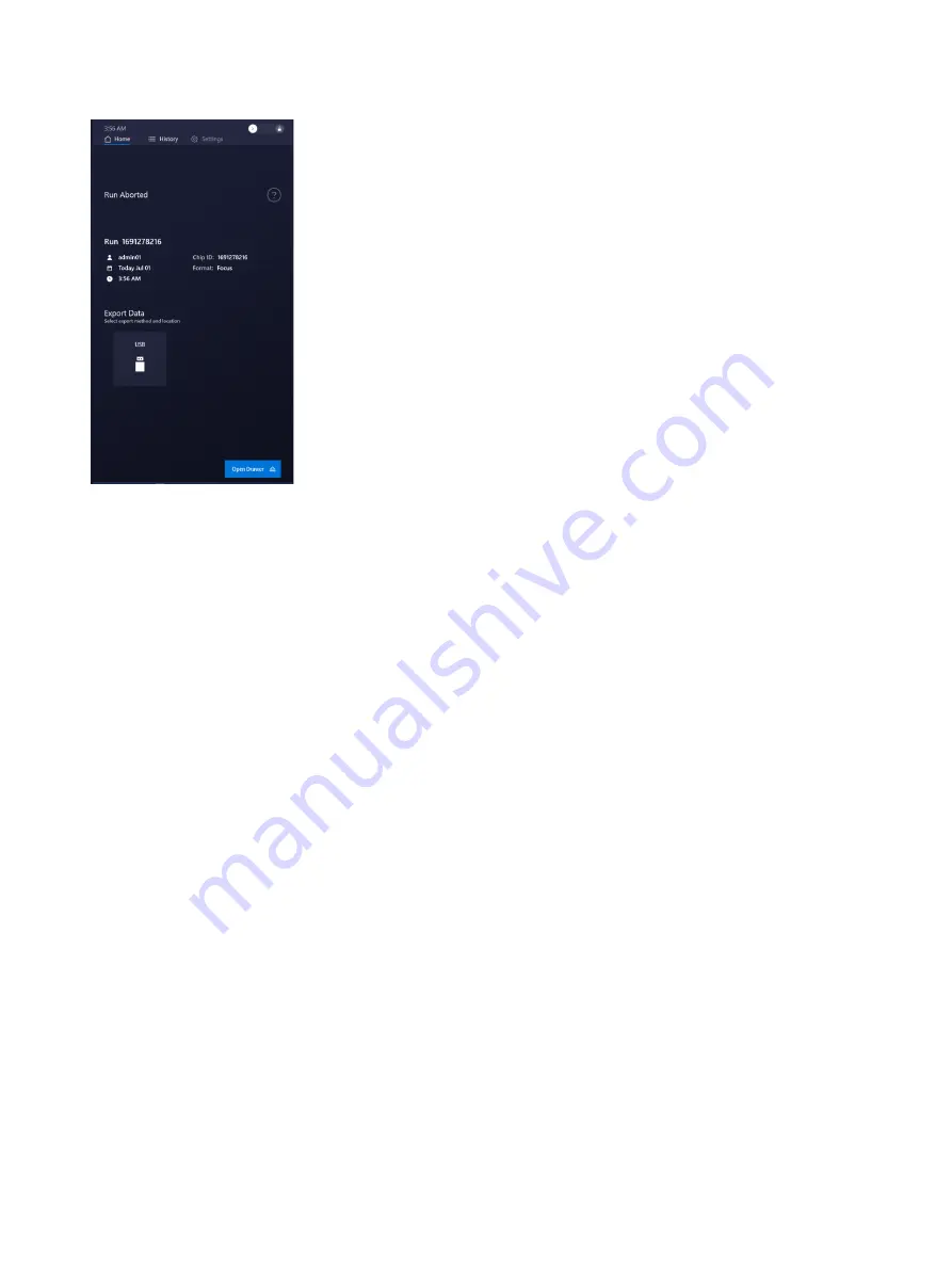
background image

2.  Tap 

Open Drawer

, then remove the chip and interface plate.  

3.  Tap 

Close Drawer

 to return to the Home screen.

5.9  Idle mode

The instrument goes into idle mode automatically when there is no user interaction for a long while.  
Touch the screen to take the instrument out of its idle mode.

51

Summary of Contents for Signature Q100

Page 1: ...Olink Signature Q100 User Manual 1172 v1 1 2022 01 25...

Page 2: ...s 28 4 1 Workflow Overview 28 4 2 Olink Target Workflows with the 96 96 and 48 48 chip 30 4 3 Olink Focus Workflow with the 24 192 chip 40 5 Troubleshooting 48 5 1 Run Instrument Checks 50 5 2 Export...

Page 3: ...alerts for chemicals Indicator Description Pictogram see example consisting of a symbol on a white background within a red diamond shaped frame Refer to the individual safety data sheet SDS for the ap...

Page 4: ...from Olink either alone or as part of this kit go to olink com and search for the SDS using either the product name or the part number Some chemicals referred to in this user guide may not have been...

Page 5: ...ets of primers This innovative solution for real time PCR provides experiment densities far beyond what is possible with microplate platforms significantly reducing the number of liquid handling steps...

Page 6: ...h the Olink Signature Q100 system Component Label Color Supported chip Olink Signature Q100 Interface Plate 96 96 96010 Green Olink 96 96 chip for Protein Expression Olink Signature Q100 Interface Pla...

Page 7: ...mm tubing into the compressed air inlet on the rear of the system and regulate the incoming air to 80 90 psi or 5 5 6 2 bar of CDA POWERED BY FLUIDIGM LAN AC 100 240V 50 60Hz 8A USB USB HDMI COMPRESS...

Page 8: ...be reached Damage control and limitation in case of an incident via the smaller attack surface A smaller subset of network devices is within the same scope Improved access control for external and int...

Page 9: ...networks can be established if the scenario requires it 2 8 Regulatory Compliance The following directives and harmonized standards were used to evaluate the safety and performance of the Olink Signa...

Page 10: ...ink Signature Q100 System Software 3 1 1 Unlock the Touchscreen Swipe toward the unlock icon to unlock the touchscreen 3 1 2 Log In to the Olink Signature Q100 System If required enter your username a...

Page 11: ...passwords To access the User Accounts settings you must have an account that has Manager permissions see section 3 2 User Accounts Instrument Check Run instrument checks on the Olink Signature Q100 in...

Page 12: ...ructions for how to perform the tasks required for that step of the workflow To close the on screen help window tap in the top right corner 3 1 5 View Run Logs and Export Data Tap History to view run...

Page 13: ...port The files are copied to the USB drive A Success message is displayed when the export is complete If there was a problem with the run Technical Support might request the raw data files for that ru...

Page 14: ...o export 3 Tap Export The files are copied to the USB drive A Success message is displayed when the export is complete 3 1 6 Delete Run Files After you export run files you can delete them from the in...

Page 15: ...exported run files In the History screen exported runs show a checkmark in the right column NOTE Run files must be exported before they are deleted 1 Go to the History screen 2 Tap or in the Export c...

Page 16: ...3 1 8 Change System Time Settings 1 Tap Settings System then tap Edit next to Time Settings 2 Change the time zone and the date and time then tap OK 16...

Page 17: ...3 To view the time in 24 hour format select the 24 Hour Format checkbox 4 Tap Save Changes Tap Yes to update the system settings If you do not want to keep your changes tap Cancel 17...

Page 18: ...e system settings Tap Cancel if you do not want to keep your changes For information about running instrument checks manually see 5 1 Run Instrument Checks 3 1 10 Change the Screen Lock Timeout 1 Tap...

Page 19: ...the Require Authentication checkbox then tap Save Changes 4 Tap Yes to update the system settings If you do not want to keep your changes tap Cancel After enabling authentication you can access the U...

Page 20: ...t to request a recovery key The Olink Signature Q100 system has three types of user accounts Account Type Description Manager Managers can Log into the system Start new runs and abort runs started by...

Page 21: ...or Operator 5 Tap Save 3 2 2 Disable a User Account A user with a Disabled account is no longer allowed to log in but the account is still in the system for auditing purposes IMPORTANT To disable a us...

Page 22: ...tails screen 4 Tap 5 Tap Yes sure to delete the user account If you do not want to delete the user account tap No 3 2 4 Change Your Password When Authentication is enabled a user with an Operator acco...

Page 23: ...g particulates reagents and fluids to the chip surface 3 3 2 Bubble Prevention Vortex the 96 well primer and sample plates gently low speed but thoroughly at least 5 sec to allow all reagents to mix h...

Page 24: ...epare the chip on Signature Q100 This primes the chip ready for use Remove the chip from the instrument and pipet each final sample and primer mix into the chip 3 Run the chip and collect data on Olin...

Page 25: ...uid Do not evacuate air from a syringe before injecting control line fluid Step 4 Optional step to ensure proper chip function 2 Actuate the check valves a Place the chip on a flat surface b Use the s...

Page 26: ...proximately 5 sec before withdrawing the syringe Before removing the syringe from the accumulator ensure that all the control line fluid and air are purged from the syringe This is to avoid dripping f...

Page 27: ...displayed on the screen tap 3 After you tap Target 96 or Target 48 the drawer opens 4 Place the chip containing control line fluid and the interface plate on the drawer Align the notched corner of th...

Page 28: ...eturn to the Insert a chip with control line fluid into the instrument screen 6 Tap Start Preparation begins and displays the time remaining NOTE If you need to abort the preparation tap Abort at the...

Page 29: ...p Eject in the bottom right corner to open the drawer 8 Remove the chip and interface plate from the instrument then tap Close Drawer IMPORTANT Do not leave the drawer open while you are pipetting sam...

Page 30: ...orientation of the A1 corner The barcoded edge is on the left side NOTE Olink recommends using the reverse pipetting method when pipetting the sample and primer mixes See the Olink Target 96 User Manu...

Page 31: ...If required login to the Olink Signature Q100 instrument 2 On the Pipette samples and primers onto the chip screen tap Open Drawer NOTE Olink Target 48 chip screen shown 3 Make sure that the Inteface...

Page 32: ...the following details for the run Run Name the default name is the Chip ID Max number of characters is 100 Run Notes NOTE If you need to eject the chip tap Eject at the bottom of the screen The softw...

Page 33: ...drive into the USB port on the front of the instrument b On the Run Successfully Completed screen tap Export Data to copy the run data to the USB drive NOTE You can export the data files later from th...

Page 34: ...instrument 10 Tap Close Drawer 11 Return the interface plate to the storage container Discard the used chip 12 Analyze the exported data using the NPX Signature software NOTE You can export data onto...

Page 35: ...ion 2 Actuate the top check valve a Place the chip on a flat surface b Use the syringe with the shipping cap to actuate the check valve in the top accumulator with gentle pressure Ensure that the popp...

Page 36: ...chip surface Residual control line fluid or air in the pipette tip is normal 7 Make sure that the O ring returns to its normal position after the syringe is removed 8 Pull the protective film down and...

Page 37: ...chip 5 Pipet 20 L of Pressure Fluid into each of the P4 and P5 inlets on the chip 6 Place the Olink Signature Q100 Interface Plate 24 192 over the chip aligning the barcoded edges 7 Use clear tape to...

Page 38: ...k Signature Q100 NOTE If you see the Lock icon swipe it to unlock the system 1 If required log in to the Olink Signature Q100 instrument 2 On the Start a New Run screen tap Focus NOTE For more informa...

Page 39: ...late and Chip Notched corner in chip and drawer 5 Tap Close Drawer The system scans the chip barcode then closes the drawer 6 On the Add run details screen confirm the Chip ID then enter any of the fo...

Page 40: ...run begins and the screen displays the time remaining NOTE If you need to abort the run tap Abort at the bottom of the screen See 5 8 Abort a Run in Progress for more information 8 When the run is com...

Page 41: ...n the Run Successfully Completed screen tap Export Data to copy the run data to the USB drive NOTE You can export the data files later in the History screen See 3 1 5 View Run Logs and Export Data for...

Page 42: ...n the interface plate to the storage container Discard the used chip 13 Analyze the exported data using the NPX Signature software NOTE You can export data onto a USB drive or access it using ethernet...

Page 43: ...uum Dust on the bottom of the chip or the top of the thermal chuck Confirm that the protective film was removed from the chip prior to loading on the tray Clean the thermal chuck using a lint free clo...

Page 44: ...n Demonstration mode by mistake Contact Olink Technical Support to change the instrument back into Run mode Chip scan error Chip was loaded without its Interface plate on Repeat loading with correct I...

Page 45: ...all components are connected and communicating properly The quick check takes 5 8 min to complete NOTE If a chip is located in the instrument it is not possible to execute the Run Instrument Checks R...

Page 46: ...logs as follows 1 Insert a USB drive into the USB port on the front of the instrument 2 Tap select the date range for the logs you want to export then click Export The logs are exported to the USB dr...

Page 47: ...USE T8AL 250VAC Main power switch Fuse holder blocks 3 Replace the fuse T8AL 250 VAC 5 20 mm and reinstall the fuse holder Follow the arrow marks in the fuse holder to match the casing 4 Plug the powe...

Page 48: ...sure that the system components are working correctly Initialization and the instrument checks take approximately 10 min to complete Export the results from the Instrument Check screen under Settings...

Page 49: ...h system shutdown NOTE If a run is in progress the screen displays a message NOTE You can either abort the run and shut down or wait until the run is complete before trying to power down the system ag...

Page 50: ...l The system starts up and the instrument initializes all system components and software It also performs a set of instrument checks to ensure that the system components are working correctly The syst...

Page 51: ...interface plate 3 Tap Close Drawer to return to the Home screen 5 9 Idle mode The instrument goes into idle mode automatically when there is no user interaction for a long while Touch the screen to t...

Page 52: ...to cool down after a completed run AUTION C HOT SURFACE HAZARD The thermal cycler chuck gets hot and can burn your skin Use caution when working near the chuck 2 Tap Open Drawer 3 Remove the chip and...

Page 53: ...ean the Instrument and Touchscreen Use a lint free cloth and 70 ethanol or 70 isopropyl alcohol to gently wipe the top of the instrument drawer and the instrument covers as needed Wipe down the touchs...

Page 54: ...nd Biomedical Laboratories BMBL a publication from the Centers for Disease Control and Prevention and your lab s safety protocol to limit biohazard risks If biohazardous materials are used label the e...

Page 55: ...inated surfaces with a wet cloth to remove residual alcohol and wipe dry 6 2 3 Disposal of Products Used chips and reagents should be handled and disposed of following federal state regional and local...

Page 56: ...7 Technical support For technical support contact support olink com 56...

Page 57: ...8 Revision history Version Date Description 1 1 2022 01 25 Added text to section 2 7 Editorial changes 1 0 2021 11 11 New 57...

Page 58: ...related documents Title Document Number Olink Target 96 User Manual 0935 Olink Target 48 User Manual 1141 Olink Signature Q100 Site Requirements Guide 1170 Olink NPX Signature User Manual 1173 Olink S...

Page 59: ...from the Centers for Disease Control and Prevention and your lab s safety protocol to limit biohazard risks If biohazardous materials are used label the equipment properly as a biohazard For more info...

Page 60: ...wer and standby symbol Rear of instrument The Power switch is in the Off position Rear of instrument The Power switch is in the On position Inside of instrument for service personnel only Protective c...

Page 61: ...ceable by the user ARNING W ELECTRICAL HAZARD Plug the system into a properly grounded receptacle with adequate current capacity 10 4 Chemical Safety The responsible individuals must take the necessar...

Page 62: ...dures All information in this publication is subject to change without notice Trademarks Olink and the Olink logo are trademarks or registered trademarks of Olink ProteomicsAB in the United States and...

Reviews: