CONNECTING
PAGE
|
35
6
Adjust the jam nuts on the on either side of the support bracket to hold the filter assembly in
position.
7
Connect nitrogen or breathing-grade air to the straight connector using 1/4-inch plastic tubing.
8
Set a purge pressure between 13.8–34.5 kPa (2–5 PSI). This provides just enough positive airflow
to prevent dust from entering the laser. If a flowmeter is available, set a flow rate of 0.85–1.7
m
3
/hr.
(30–60 SCFH, Standard Cubic Feet per Hour) at a pressure not to exceed 34.5 kPa (5 PSI).
9
When purge gas is flowing, access the i401’s web page and monitor the Relative Humidity value.
The measured value should drop to 0% (± 10%) within 10–15 minutes. If the relative humidity
never drops below approximately 10%, then increase the flow rate slightly.
Important Note:
To disconnect gas purge tubing, first push and hold the tubing slightly into the
fitting. Next push the release collet evenly towards the fitting, and then pull the tubing free.
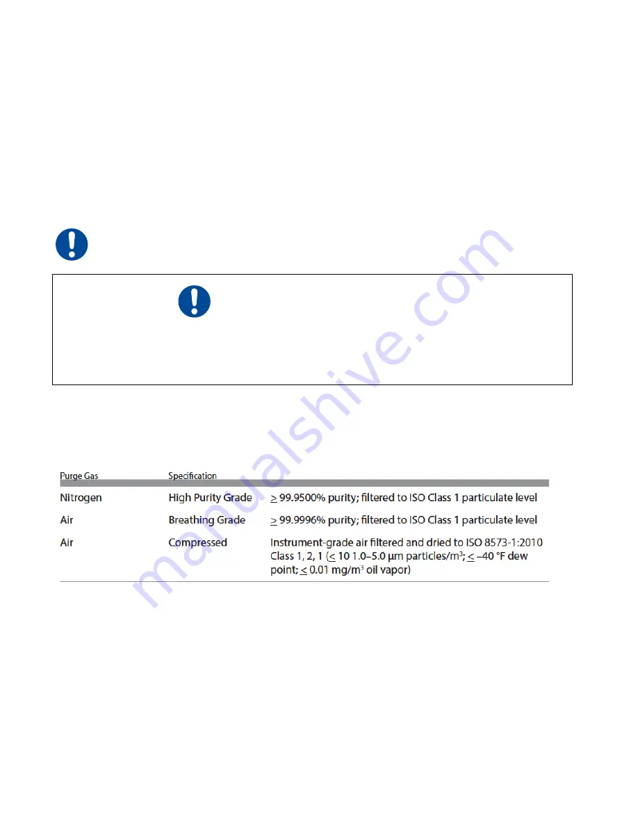
The Gas Purge port on the i401 laser must be connected to a source of nitrogen or clean, dry air only; do
not use any other gases for purging. Purge gas specifications are listed in Table 1-4 below.
Table 1-4 Purge gas specifications
Ethernet port
A connection to the i401 Ethernet port is not required for normal operation; however, we strongly
recommend that you setup the i401 web page and verify its functionality as part of the initial start-up
procedure. This will ensure an i401 web connection is available for troubleshooting purposes if necessary,
during preliminary testing of the i401 laser.
Caution: Possible Equipment Damage
Do not exceed a gas purge pressure of 34.5 kPa (5 PSI). Excessive pressure may damage the
purge assembly or other internal laser com- ponents.
Do not use argon as a purge gas. Use only nitrogen or clean, dry air as described in Table 1-4,
Purge gas specifications.


