background image

- 1 - 

1. 

Outline 

 
MR210AU/220AU is a motion control unit which can control one or two axes of either stepper motor or pulse type servo drives 
for position and speed controls. A built-in EEPROM can program driving parameter values and position data of up to 64 steps for 
each axis. MR210AU controls 1-axis and MR220AU controls 2-axes.   
 

Model 

Axes 

Serial Communication Port 

MR210AU 

equipped with RS-232C, USB. 

MR220AU 

equipped with RS-232C, USB. 


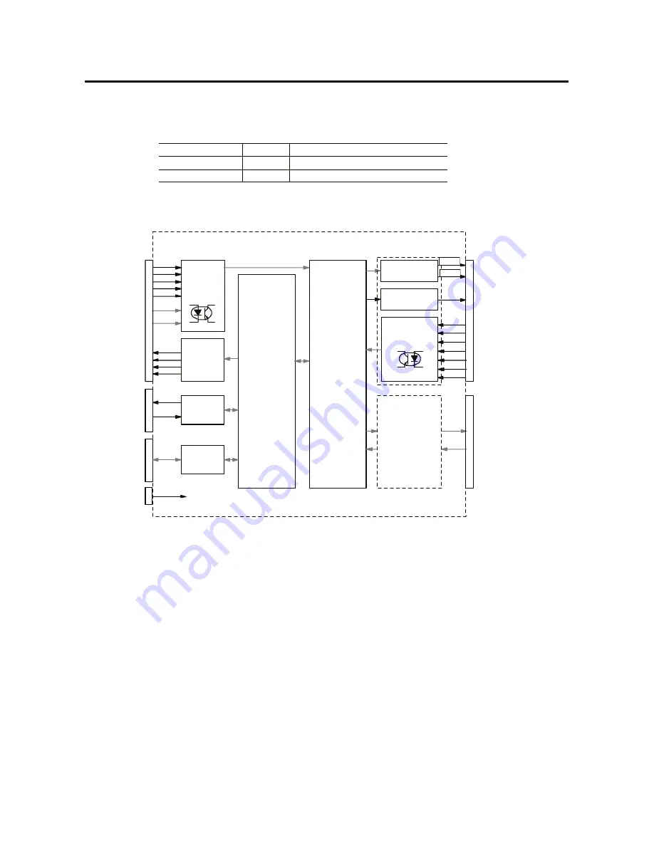
Fig.1.1 shows the MR210AU/220AU basic circuit block diagram. 


A 2-axes motion control IC “MCX302” is equipped with acceleration/deceleration drive pulse oscillation of up to 4MHz and a 
position counter. 
 
Driving pulse output to a motor driver is differential line-drive output, which can connect to the motor driver of either photo 
coupler input or differential line receiver input.     
 
Sensor input is insulated by photo coupler, which can input over run limits, a home, an in-position and alarm signal from a servo 
motor driver. 
 
Serial communication port has two interfaces, RS232C and USB. Connect the serial communication port and PC or a remote box 
(option), then set data such as driving parameter mode, position data and program data. In addition, serial communication 
commands are prepared so that the user can freely control the axis by programming on Windows. 
 
Parallel interface port performs actual drive activation, stop, position and program selection, which connects to a PLC or switches. 


Singl e Chip
Microcomputer

L in e- Dr iver

AM26C31

O utp ut Buffer

TD62083A

Photo Cou pler

X- Ax is I/ F

Y-Axis I/F

DC 2 4V

P o we r

Fig.1.1 MR210AU/220AU Circuit Block Diagram

T89C51ED2

Photo

Output Buffer

TD62083A

+ D ir e ct i on

- D ir e ct i on

Ge n er a l Ou t pu t

+ D ir e ct io n L i mi t
- D i re c ti on Li m it

S e rv o P o si ti o ni n g

Se rv o A l er m

En c od e r Z- P ha s e

H o me

Ne a r Ho m e

MAX232C

P ar a ll e l

I/ F

I/ F

RS -2 3 2C

MCX302

X OU T0

XL MT +
XL M T-

X S TO P 0

XS TO P 1
XS TO P 2

X I NP O S
X A LA RM

T X

R X

RE SE T
HO M E

S TR O BE

X

Y

R EG 0 ~ 5

M OD E0 ~ 1

X D RI V E
Y D RI V E

CN1

CN2

CN3

O pen

CN4

Y - Ax i s I/ O S i gn a l

( Sa me as X- A xi s)

2-Ax es Motion
Control IC

TLP281

Co llector

XE R RO R

YE R RO R

EEPROM

FT

232

R

CN6

U S B I/ F

TLP281

CN5

[Note1] MR210AU does not have CN5.

N o te 1

注1

XP + P/ N

X P- P /N

Built-in

Cou pler

I n p u t

P u l s e O u t p u t

P u l s e O u t p u t

C om p le ti o n

Summary of Contents for MR210AU

Page 1: ...1 2 Axes Motor Control Unit MR210AU MR220AU User s Manual 2004 02 18 Ver 1 0 2007 04 04 Ver 1 1 2008 12 12 Ver 3 3 2010 06 30 Ver 3 4 NOVA electronics...

Page 2: ...y or material damages This mark indicates the user that improper use may cause damage to the equipment or the loss of valuable data General Safety Instructions Do not use the equipment in locations su...

Page 3: ...ftware When using serial communication instead of the provided software refer to serial communication commands book RS232C and USB cables are prepared as communication cables MR210AU MR220AU can conne...

Page 4: ...Setting 18 3 3 1 The Description of Home Search Operation 18 3 3 2 Home Search Mode Setting 19 3 3 3 Example for Home Search Mode Setting 22 4 Driving Program 25 4 1 Driving program commands 25 4 2 I...

Page 5: ...ng Mode and Parameters 51 7 1 5 One Command Execution 52 7 2 Drive Operation 52 7 2 1 Home Search 52 7 2 2 Jog Feed 53 7 2 3 Program Execution 53 7 2 4 Current Position Writing 54 8 Input Output Signa...

Page 6: ...has two interfaces RS232C and USB Connect the serial communication port and PC or a remote box option then set data such as driving parameter mode position data and program data In addition serial com...

Page 7: ...with the cable that comes with the package then set driving parameter mode and programs by the operating program installed in step 1 These setting data will be written in a built in EEPROM In addition...

Page 8: ...e operating program the user can perform manual operations such as jog feed of each axis home search and program execution from main operational panel See chapter 6 c Activation from Remote Box Connec...

Page 9: ...32C communication follow steps in chapter 2 3 2 1 Operating Program Installation 2 1 1 Operating Program Installation 1 Insert MR200 Series CD ROM into the CD drive Note Do not connect MR210AU 220AU a...

Page 10: ...5 5 On the Select Installation Folder screen click Next which uses the default settings 6 On the Confirm Installation screen click Next 7 On the user s account control click Yes Only on Windows 7...

Page 11: ...6 8 MR220A is now installed 9 When the installation is complete the Installation Complete screen appears Click Close to complete setup...

Page 12: ...indows Control Panel Or on windows 7 use Program Program and function and Uninstallation or change of program 2 Select the MR220A program from the list then click Add Remove button The operating progr...

Page 13: ...ompleted Note1 Installation Wizard appears twice Note2 USB driver installation is needed once every unit For example if 3 units are connected to PC USB driver should be installed three times 2 2 2 Che...

Page 14: ...nection the following error message appears After clicking OK communication open error message appears Click OK 5 Select Style dialog box appears click the type MR220AU or MR210AU which the user uses...

Page 15: ...rating program When the main screen appears click Parameter Mode button Parameter Mode screen appears Parameter Mode screen has three tabs Mode Parameter and Home Search Mode Hereinafter describe how...

Page 16: ...rm input signal from a servo motor driver Display Option Default Servo Alarm Enable Servo Alarm Level Disable Enable Low GEX Short circuited High Open Disable Low Servo alarm input signals nALARM of e...

Page 17: ...pulses outputs of specified driving pulses are not completed at deceleration of index driving even if the speed reaches the initial speed and remaining driving pulses are output at initial speed beco...

Page 18: ...rch operation Note 1 When using Power On Program Start write timer command to REG00 in advance then make sure that next command is operated after passing the specified period In addition it recommends...

Page 19: ...ed but speed resolution becomes rough Set the minimum value which covers the range of drive speed Acceleration Rate Acceleration Rate is the parameter used as acceleration rate at acceleration in acce...

Page 20: ...iplier When drive speed is larger than this start speed acceleration deceleration driving is performed In this case the parameter of acceleration deceleration rate must be set When drive speed is smal...

Page 21: ...Home search high speed usually sets larger value than start speed to perform acceleration deceleration driving Home Search Offset Sets offset drive for home search If 0 is set offset drive is not per...

Page 22: ...ion data is displayed the coefficient shown in the right formula is multiplied and then the value will be displayed For example if 1 pulse of driving pulses is equivalent to 0 01mm of moving distance...

Page 23: ...tep 2 Step 2 Low speed Home Search Driving pulse is output in the specified direction at the speed which is set in the parameter of home search low speed until home signal nSTOP1 becomes active To per...

Page 24: ...is set in the parameter of home search high speed driving pulses set in home search offset are output in the specified direction This is used when the user wants to move the axis from mechanical home...

Page 25: ...ignals nSTOP2 of each axis are the 9 pins in CN4 5 connectors See chapter 8 When an active logical level is set to low detection operation of step 3 starts and when the signal becomes short circuiting...

Page 26: ...cannot be used as general purpose output Deviation counter clear output becomes active at the same time as detection of Z phase in step 3 and starts step 4 after finishing clear pulse output Deviatio...

Page 27: ...p 1 When starting position is in point B as shown in the diagram irregular operation 2 of step 2 is performed after the limit is set in the search direction in step1 Note 1 Make sure to set an over ru...

Page 28: ...e from the limit Operation Input signal and logical level Search Direction Search Speed Step 1 STOP0 Low GEX Short circuited 10 000pps Step 2 STOP1 Low GEX Short circuited 200pps Step 3 Non execution...

Page 29: ...al level Low The same logical level as the limit signal since the limit signal is used Home Signal Level nSTOP1 logical level Low same as above Z Signal Level nSTOP2 logical level Low Not used Step 1...

Page 30: ...Execute from the remote box See chapter 7 2 there are three ways as above Please refer to each chapter Start Operating Program Connect MR210AU 220AU and PC with the cable and then start the operating...

Page 31: ...es moving first next register step will be executed after another axis finishes moving To use Both function please note the following When Both 1 is set by ABS INC and HOM commands of X axis the same...

Page 32: ...ut Condition Jump CMD Data1 Data2 IJP Input Port Number Register Number to Jump When the specified input port is Low GEX short circuited it jumps to the specified register When not Low Open it moves t...

Page 33: ...o Repetition End command RPE Data Specifies the repetition numbers The range is from 1 to 255 Repetition End command RPE must be placed under this Repetition Start command REP larger register number R...

Page 34: ...Timer CMD Data TIM Waiting Time msec Waits for the specified period Data Specifies the waiting time in a unit of msec The range is from 0 to 65535 msec NOP No Operation CMD Data NOP No operation is pe...

Page 35: ...Home YSTOP1 Home YSTOP2 Encoder Z phase YINPOS Servo Positioning Completion Y axis Signals REGSL0 REGSL1 REGSL2 REGSL3 REGSL4 REGSL Signal Parallel I F Signals When using MR210AU 10 13 is not availab...

Page 36: ...ns ON the axis designation signal X 4 Y 5 and HOME 2 input signal is ON for more than 10msec The figure below shows an example for a home search of X axis only Once home search starts nDRIVE END 14 15...

Page 37: ...individually and another is the Scan Driving 2 which can drive 2 axes individually Scan Driving 1 Scan driving 1 drives in the or direction respectively with axis designation signal X 4 Y 5 while RUN...

Page 38: ...n each direction while the input signal below is ON Axis and Direction for Scan Driving Input Signal to turn ON axis Direction SCANX 6 axis Direction SCANX 7 axis Direction SCANY 4 axis Direction SCAN...

Page 39: ...perating program on your PC according to the following steps 1 Connect the motor control unit and PC with the RS232C or USB cable Be sure not to connect with both cables 2 Turn on both equipment power...

Page 40: ...Control Panel System Hardware tab Device Manager the user can find the COM port number after USB device driver name USB to Serial Port under Ports COM LPT 6 2 Main Screen When starting the operating...

Page 41: ...as follows Set Drive Speed 1 from Main Operation Window and start driving It drives at Drive Speed 1 Set Drive Speed 3 with Parallel Interface It drives at Drive Speed 3 Jog Operations Display Operati...

Page 42: ...ABS INC HOM OUT and OTP commands are available Stop When clicking the button after a click of Run the program step now executed becomes PAUSE Then if Stop is clicked again the program is aborted If R...

Page 43: ...220AU Data is read from the motor control unit All All the data Program All All the programs Program Xaxis X axis program data Program Yaxis Y axis program data Parameter All All the data of Parameter...

Page 44: ...automatically downloaded to the motor control unit Setting items in Mode tab are as follows See chapter 3 1 for more details on each mode Display Contents Option Default Limit Stop Mode Limit stop mod...

Page 45: ...tion Rate 1 8000 400 Deceleration Rate 1 8000 400 Start Speed 1 8000 50 Drive Speed 1 1 8000 10 Drive Speed 2 1 8000 100 Drive Speed 3 1 8000 1000 Drive Speed 4 1 8000 8000 Post Timer 1 1 65535 msec 1...

Page 46: ...gical level Low High Low Step 1 Enable Step 1 enable disable Disable Enable Disable Step 1 Direction Step 1 search direction Step 2 Enable Step 2 enable disable Disable Enable Disable Step 2 Direction...

Page 47: ...nted by one When online mode the data is automatically downloaded to the motor control unit Input Item Command Contents Command Select command by click ABS Absolute position move OUT Output port ON OF...

Page 48: ...re shown as follows The user can cut copy and paste a selection in the display area Item Function Contents Cut Clear a selection Copies a selection in the display area to clip board and clears the sel...

Page 49: ...turns on a light when the signal is active For instance if Limit Active Level is low in mode setting limit signal nLMT turns on a light when the signal is short circuited with GEX The input signal of...

Page 50: ...Device control block of Port was received Unexpected error that device control block DCB of port was received 408 There is no response Command cannot be received 501 X Axis is already driving now Ano...

Page 51: ...ng mode Parameters and Programs writing One command execution Register Number Drive Operation Current Position Display Jog Feed Home Search Program Execution Operation panel of the remote box is as fo...

Page 52: ...and the value returns to the previous one Increases and decreases the displayed register number EXC Executes the displayed command However only ABS INC OUT OTP and HOM1 4 commands are available DP Swi...

Page 53: ...ch pressing the key 7 1 2 Register Configuration Register configuration displayed by the remote box is as follows Data Type Remark REG Number Contents Number Data Mode Data 00 63 Driving programs 64 7...

Page 54: ...ess WRT Position data flushes twice to inform registration completion Press WRT Status becomes command input and ABS blinks Select command by keys Select any of HOM1 HOM4 Press WRT Display flushes twi...

Page 55: ...99 msec If the number beyond the range is already registered on PC the pulse width is not displayed Press WRT Status becomes command input and ABS blinks Select command by keys Press WRT Display flush...

Page 56: ...e 1 Enable 4 Inposition Signal Level 0 GEX Short circuited 1 Open 5 Alarm 0 Disable 1 Enable 6 Alarm Signal Level 0 GEX Short circuited 1 Open REG72 Driving Mode 2 Display Contents of each digit in DA...

Page 57: ...to drive operation In drive operation the current position of the selected axis is displayed in DATA As shown on the left side of input keys in yellow the upper row of keys is for X axis and the lowe...

Page 58: ...r Program execution can perform for only X axis only Y axis and for both X and Y axes simultaneously While driving X axis Y axis cannot be executed and while driving Y axis X axis cannot be executed O...

Page 59: ...speed can be switched 4 Press X Y key to select the axis The light of the selected axis turns on Current position writing performs each axis and cannot perform X and Y axes simultaneously 5 Press WRT...

Page 60: ...GND Signal ground 4 nothing is connected 5 nothing is connected 6 nothing is connected For reference the internal wiring diagram of the accessory RS232C cable is as follows Connector Connector Type O...

Page 61: ...9 REGSL3 SPD1 Input Register designation 3 Drive speed 1 A1 10 REGSL4 SCAN Input Register designation 4 Scan A1 11 REGSL5 STOP Input Register designation 5 Drive stop A1 12 MODE0 Input Driving mode de...

Page 62: ...GSL2 SPD0 Pin 8 Input Register designation 2 Drive Speed 0 REGSL3 SPD1 Pin 9 Input Register designation 3 Drive Speed 1 REGSL4 SCAN Pin 10 Input Register designation 4 Scan REGSL5 STOP Pin 11 Input Re...

Page 63: ...alid in mode setting of the motor control unit Home Search Turns ON while running home search and turns OFF after the end of driving Turns OFF while runnning home search and outputs driving end pulse...

Page 64: ...tion n X Y nP N Pin2 Output Driving pulse negative output in the direction nP P Pin3 Output Driving pulse positive output in the direction nP N Pin4 Output Driving pulse negative output in the directi...

Page 65: ...STOP0 Pin11 Input Near home Input signal for home search See chapter 3 3 Home Search Mode Setting for home search operation Description 14 nLMT Pin12 Input Limit in the direction n X Y nLMT Pin13 Inpu...

Page 66: ...ion RS232C USB LED4 X Turns on a light during driving of X axis and blinks at the error LED5 Y Turns on a light during driving of Y axis and blinks at the error LED4 5 turn on a light for 0 2 seconds...

Page 67: ...Position Move Relative Position Move Home Search I O IJP OUT OTP Input Condition Jump Output Port ON OFF Output Port ON Pulse Program Control JMP REP RPE END TIM NOP Jump Repetition Start Repetition...

Reviews: