34
Chapter 2 Cabling the gateway and turning the power on
314711-D Rev 00
Understanding the LEDs
This section describes the LEDs on the front panel of the Contivity 1700 and on
the interface cards that have LEDs. You can confirm that the LAN and WAN
interfaces are cabled properly by examining the LEDs.
Front panel LEDs
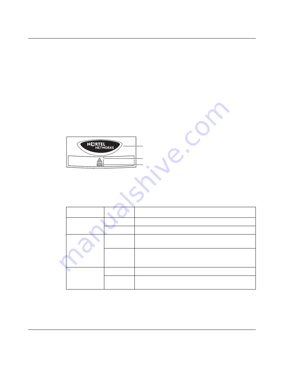
The front panel of the Contivity 1700 has a lighted Nortel Networks logo and two
LEDs
(Figure 8)
. These LEDs indicate the status of the Contivity 1700.
Figure 8
Front panel LEDs
Table 4
describes the LEDs on the Contivity 1700 front panel.
For complete information about the health check, event log, and system log, see
Managing and Troubleshooting the Contivity Secure IP Services Gateway
.
Table 4
Front panel LED indicators
LED
Indicator
Description
Power (Nortel
Networks logo)
On
The gateway is receiving AC power.
Off
The gateway is not receiving AC power.
Alert/Fail
Yellow
A non-fatal alarm condition exists. The yellow alert
condition is described in the health check display.
Red
A serious alarm condition exists that requires attention.
A red alert usually indicates a hardware error. The red
alert condition is described in the health check display.
Boot/Ready
Yellow
The gateway is booting and is in a non-ready state.
Green
The boot process has completed successfully and the
gateway has reached a state of readiness.
Alert/Fail
Boot/Ready
CS160013A
Power
Alert/Fail
Boot/Ready
Summary of Contents for 1700
Page 6: ...6 314711 D Rev 00 ...
Page 10: ...10 Contents 314711 D Rev 00 ...
Page 14: ...14 Tables 314711 D Rev 00 ...
Page 28: ...28 Chapter 1 Installing the Contivity 1700 chassis 314711 D Rev 00 ...
Page 42: ...42 Chapter 2 Cabling the gateway and turning the power on 314711 D Rev 00 ...
Page 50: ...50 Chapter 3 Configuring the management IP interface 314711 D Rev 00 Figure 16 Welcome screen ...
Page 52: ...52 Chapter 3 Configuring the management IP interface 314711 D Rev 00 ...
Page 88: ...88 Appendix A Technical specifications 314711 D Rev 00 ...
Page 94: ...94 Index 314711 D Rev 00 ...


