background image

Chapter 2  Cabling the gateway and turning the power on  

35

Installing the Contivity 1700


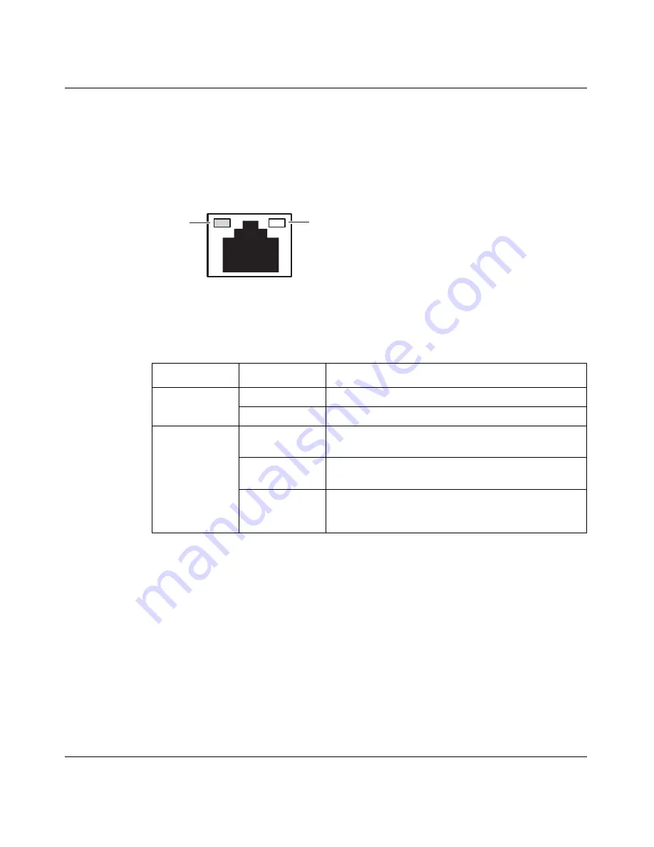
LEDs on the system 10/100BASE Ethernet port

Figure 9

 shows the LEDs for the 10/100BASE Ethernet port located on the rear of 

the Contivity 1700.

Figure 9   

LEDs on the system 10/100BASE Ethernet port

Table 5

 describes the LEDs on the system 10/100BASE Ethernet port. 

Table 5   

LED indicators on the system 10/100BASE Ethernet port

LED

Indicator

Description

Green 

On

The LAN port is operating at 100 Mb/s.

Off

The LAN port is operating at 10 Mb/s.

Yellow

On

The cable connections between the LAN port and the 
hub are good.

Off

The cable connections between the LAN port and the 
hub are faulty. 

Flashing

The LAN port is sending or receiving network data. 
The frequency of the flashes increases with 
increased traffic.

CS260011A

Green

Yellow

Summary of Contents for 1700

Page 1: ...Part No 314711 D Rev 00 June 2004 600 Technology Park Drive Billerica MA 01821 4130 Installing the Contivity 1700 314711 D_Rev_00 ...

Page 2: ...without notice Nortel Networks Inc does not assume any liability that may occur due to the use or application of the product s or circuit layout s described herein USA requirements only Federal Communications Commission FCC Compliance Notice Radio Frequency Notice Note This equipment has been tested and found to comply with the limits for a Class A digital device pursuant to Part 15 of the FCC rul...

Page 3: ...99 5 EC Japan Nippon requirements only Voluntary Control Council for Interference VCCI statement Taiwan requirements Bureau of Standards Metrology and Inspection BSMI statement Canada requirements only Canadian Department of Communications Radio Interference Regulations This digital apparatus Contivity 1700 does not exceed the Class A limits for radio noise emissions from digital apparatus as set ...

Page 4: ... or distribute the Software except as expressly authorized b reverse assemble reverse compile reverse engineer or otherwise translate the Software c create derivative works or modifications unless expressly authorized or d sublicense rent or lease the Software Licensors of intellectual property to Nortel Networks are beneficiaries of this provision Upon termination or breach of the license by Cust...

Page 5: ...Customer fails to comply with the terms and conditions of this license In either event upon termination Customer must either return the Software to Nortel Networks or certify its destruction c Customer is responsible for payment of any taxes including personal property taxes resulting from Customer s use of the Software Customer agrees to comply with all applicable laws including all applicable ex...

Page 6: ...6 314711 D Rev 00 ...

Page 7: ...onal equipment 22 Cables 22 Hardware for mounting the chassis in an equipment rack 22 Site requirements 22 Installing the chassis 23 Installing the chassis on a flat surface 23 Installing the chassis in an equipment rack 24 Rack mount recommendations 24 Attaching the shelf in the equipment rack 24 Mounting the chassis in the equipment rack 26 Chapter 2 Cabling the gateway and turning the power on ...

Page 8: ... Required information 44 Configuring the management IP address 45 Testing the configuration 49 Troubleshooting 51 Chapter 4 Installing option cards and DIMMs 53 Shutting down the system to add or replace hardware 54 Removing the front bezel and top cover 55 Attaching the antistatic wrist strap 58 Installing and replacing option cards 59 Installing and replacing DIMMs 64 Appendix A Technical specif...

Page 9: ...ard 72 ADSL WAN interface card 74 ISDN BRI interface card 75 T1 E1 CSU DSU WAN interface card 77 Quad T1 E1 CSU DSU WAN interface card 79 V 90 modem interface card 80 Single V 35 X 21 WAN interface card 80 Dual V 35 WAN interface card 84 HSSI WAN interface card 86 Index 89 ...

Page 10: ...10 Contents 314711 D Rev 00 ...

Page 11: ...LEDs on the T1 E1 CSU DSU WAN interface card 39 Figure 14 LEDs on the quad T1 E1 CSU DSU WAN interface card 40 Figure 15 LEDs on the single V 35 X 21 WAN interface card 41 Figure 16 Welcome screen 50 Figure 17 Removing the front bezel 55 Figure 18 Removing the top cover 56 Figure 19 Location of option card slots and DIMMs on the system board 57 Figure 20 Location of the grounding jack for the anti...

Page 12: ...RI U interface card 75 Figure 32 T1 E1 CSU DSU WAN interface card 77 Figure 33 Quad T1 E1 CSU DSU WAN interface card 79 Figure 34 V 90 modem interface card 80 Figure 35 Single V 35 X 21 WAN interface card 80 Figure 36 Dual V 35 WAN interface card 84 Figure 37 HSSI WAN interface card 86 ...

Page 13: ...he single V 35 X 21 WAN interface card 41 Table 12 Supported option cards for the Contivity 1700 59 Table 13 Physical electrical and environmental specifications 67 Table 14 10 100BASE Ethernet port pinouts 69 Table 15 Multiple DB9 and DB25 connector pinouts 69 Table 16 Modem cable pinouts 70 Table 17 56 64K CSU DSU cable pinouts for crossover connection 73 Table 18 56 64K CSU DSU cable pinouts fo...

Page 14: ...14 Tables 314711 D Rev 00 ...

Page 15: ...ial configuration information and includes technical specifications for the gateway For complete information about configuring and monitoring the Contivity 1700 see the documentation on the software CD For information about Contivity documentation see Related publications on page 17 Before you begin This guide is intended for qualified service personnel who are installing the Contivity 1700 for th...

Page 16: ...book titles plain Courier text Indicates system output for example prompts and system messages Example File not found separator Shows menu paths Example Choose Status Health Check ADSL asymmetric digital subscriber line AIS alarm indication signal CSU DSU channel service unit digital service unit DIMM dual inline memory module DTE data terminal equipment HSSI High Speed Serial Interface IP Interne...

Page 17: ...ateful Firewall NAT and Contivity interface and tunnel filters Configuring Tunneling Protocols for the Contivity Secure IP Services Gateway provides instructions for configuring the tunneling protocols IPsec L2TP PPTP and L2F Configuring Advanced Features for the Contivity Secure IP Services Gateway provides instructions for configuring 802 1Q VLANs circuitless IP advanced WAN settings PPP PPPoE f...

Page 18: ...service contract for your Nortel Networks product from a distributor or authorized reseller contact the technical support staff for that distributor or reseller for assistance If you purchased a Nortel Networks service program contact Nortel Networks Technical Support To obtain contact information online go to the www nortelnetworks com cgi bin comments comments cgi URL then click on Technical Sup...

Page 19: ...itional remote access gear The Contivity 1700 provides routing firewall bandwidth management encryption authentication and data integrity services to ensure secure tunneling across IP networks and the Internet An individual user or group of users can be associated with a set of attributes that provide custom access to an extranet Note Before you install the chassis make sure that all network wirin...

Page 20: ...that can contain interface cards and one Hardware Accelerator card One 10 100 Ethernet interface card installed in PCI slot 1 128 MB memory upgradable to 256 MB total Preparing to install the Contivity 1700 Before you begin the installation verify that Your shipment is complete and undamaged You have the cables tools and other equipment that you need Your installation site meets the physical elect...

Page 21: ...pport the chassis in an equipment rack 4 10 32 panhead screws Secures the rack mount shelf to the equipment rack and the chassis to the shelf 4 10 32 panhead cage nuts Used only if the equipment rack does not have threaded rail holes 4 Rubber feet Used to install the chassis on a surface 1 Antistatic wrist strap Used to direct the discharge of static electricity from your body to the chassis to pr...

Page 22: ...k administrator Hardware for mounting the chassis in an equipment rack To install the Contivity 1700 in an equipment rack you need a Phillips screwdriver and an equipment rack that meets the following specifications Heavy duty steel construction Width of 19 in 48 26 cm and depth of 24 in 60 96 cm Electronic Industries Association EIA standard hole spacing If the rack does not have threaded rail ho...

Page 23: ...e 24 Installing the chassis on a flat surface If you decide to place the Contivity 1700 on a flat surface make sure that the surface is large enough for the gateway and sturdy enough to support the combined weight of the Contivity 1700 and the cables that you attach to it The Contivity 1700 accessory kit includes four rubber feet that can be attached to the bottom of the gateway Figure 2 shows the...

Page 24: ...ceed 40oC 104oF Do not block the power supply vents or otherwise restrict air flow when installing the chassis in a rack Stabilize your rack so that it does not tip over under the weight of the gateway and other devices Make sure that the electrical branch circuits can handle the Contivity 1700 and other units in the rack before you install and turn on the gateway Maintain a reliable earth ground ...

Page 25: ...lign the holes in the shelf with holes in the front of the rack Figure 4 Installing the shelf in the equipment rack 4 Make sure that the support flange snaps into place Figure 4 5 Insert one of the supplied panhead screws through the top hole on each side of the shelf into the hole in the rack and tighten the screw Figure 4 CS260003A Cage nut Rail without threaded holes CS260003A Flange Rack edge ...

Page 26: ... bezel from the Contivity 1700 Figure 5 a Using the Phillips screwdriver turn each of the 2 screws on the front bezel a quarter turn counterclockwise Figure 5 Removing the front bezel b Grip the two handles and firmly pull the bezel toward you to unsnap it from the chassis The first few times that you remove the front bezel it may be somewhat difficult to remove because the ball studs and socket c...

Page 27: ...ole on each side of the shelf into the hole in the rack and tighten the screws see Figure 4 on page 25 4 Replace the front bezel Figure 6 a Hold the two handles on the bezel and push it onto the chassis b Using the Phillips screwdriver tighten the 2 screws to secure the bezel to the chassis Figure 6 Replacing the front bezel CS160015A Press here ...

Page 28: ...28 Chapter 1 Installing the Contivity 1700 chassis 314711 D Rev 00 ...

Page 29: ...wing topics Caution Connect the cables to the built in Ethernet port and to the interfaces on the option cards installed in the Contivity 1700 before you plug the power cord into the outlet Topic Page Connecting communications cables 30 Connecting the power cord 32 Verifying a successful installation 33 Understanding the LEDs 34 Caution Cabling for all WAN LAN and serial connections is not to be r...

Page 30: ... for the ports from Nortel Networks For information about the connectors and cable pinouts see Appendix A Technical specifications on page 67 Table 2 Interfaces and cables for the Contivity 1700 Cable available from Nortel Networks Interface Included Ordered separately Contact supplier 10 100 Ethernet system port X Serial port X 10 100BASE Ethernet X 56 64K CSU DSU WAN X ADSL WAN X ISDN BRI X V 90...

Page 31: ...rder 1 Connect the 10 100BASE RJ 45 cable to the built in 10 100BASE Ethernet LAN port on the gateway see Figure 7 on page 31 2 If you plan to connect a terminal or PC to the gateway connect the serial cable shipped with the Contivity 1700 to the serial port see Figure 7 on page 31 3 Connect all other cables to the ports on the installed interface cards If you ordered optional interface cards conn...

Page 32: ...hat is required for your power outlet Table 3 Power cord requirements Requirement Description Current rating The power cord must be rated for the available AC voltage and must have a current rating that is at least 125 percent of the gateway s current rating 2 A 100 VAC or 1A 220 VAC Certification The power cord must have certification marks from an acceptable regional agency Cord length and flexi...

Page 33: ...perational 4 The Alert Fail LED lights yellow because the gateway is not configured For a newly installed Contivity 1700 a yellow Alert Fail LED does not indicate an alarm condition After you configure the management IP address on the gateway the Alert Fail LED turns off See Chapter 3 Configuring the management IP interface on page 43 If the LEDs on the front panel light in this sequence your inst...

Page 34: ...h check event log and system log see Managing and Troubleshooting the Contivity Secure IP Services Gateway Table 4 Front panel LED indicators LED Indicator Description Power Nortel Networks logo On The gateway is receiving AC power Off The gateway is not receiving AC power Alert Fail Yellow A non fatal alarm condition exists The yellow alert condition is described in the health check display Red A...

Page 35: ...LEDs on the system 10 100BASE Ethernet port Table 5 LED indicators on the system 10 100BASE Ethernet port LED Indicator Description Green On The LAN port is operating at 100 Mb s Off The LAN port is operating at 10 Mb s Yellow On The cable connections between the LAN port and the hub are good Off The cable connections between the LAN port and the hub are faulty Flashing The LAN port is sending or ...

Page 36: ...n the 10 100BASE Ethernet interface card Table 6 LED indicators on the 10 100BASE Ethernet interface card LED Indicator Description ACT LINK Steady green or Flashing green The card is sending or receiving network data The frequency of the flashes increases with increased traffic Off The card is not sending or receiving data 10 100TX Green The port is operating at 100 Mb s Off The port is operating...

Page 37: ...SU DSU WAN interface card Table 7 LED indicators on the 56 64K CSU DSU WAN interface card LED Description Blue Blue alarm LED is lit when receiving an upstream failure denoted by an alarm indication signal AIS Red Red alarm LED is lit when a loss of signal LOS or out of frame OOF condition is detected on the receive signal Yellow Yellow alarm LED is lit when the far end equipment is in the red ala...

Page 38: ...ion Steady green Steady green The ADSL interface card is not initialized the software driver is not installed Off Off The ADSL interface card is initialized but has not established a link with the ADSL network Flashing green Off The ADSL interface card is attempting to establish a link with the ADSL network Steady green Off The ADSL interface card has established a link with the ADSL network Stead...

Page 39: ...ce card Table 9 LED indicators on the T1 E1 CSU DSU WAN interface card LED Indicator Description LED 1 Red Red alarm LED is lit when a loss of signal LOS or out of frame OOF condition is detected on the receive signal LED 2 Blue Blue alarm LED is lit when receiving an upstream failure denoted by an alarm indication signal AIS LED 3 Yellow Yellow alarm LED is lit when the far end equipment is in th...

Page 40: ...scription LED 1 Off Port 1 is disabled On Port 1 is enabled and operating normally Flashing Port 1 is enabled and in an alarm state red yellow or blue LED 2 Off Port 2 is disabled On Port 2 is enabled and operating normally Flashing Port 2 is enabled and in an alarm state red yellow or blue LED 3 Off Port 3 is disabled On Port 3 is enabled and operating normally Flashing Port 3 is enabled and in a...

Page 41: ...s the LEDs on the single V 35 X 21 WAN interface card Table 11 LED indicators on the single V 35 X 21 WAN interface card LED Indicator Description LED 1 Red No external transmit clock source is available LED 2 Green The signals CDC and DSR are on between the DSU and the adapter LED 2 detects receive link status LED 3 Green Power to the adapter is on and the onboard microcode is loaded LED 4 Green ...

Page 42: ...42 Chapter 2 Cabling the gateway and turning the power on 314711 D Rev 00 ...

Page 43: ...procedures in this chapter you will be able to configure and manage the Contivity 1700 using a Web browser from a PC To configure the management IP interface you use the serial interface configuration menu You must connect a PC or terminal to the serial port on the Contivity 1700 This chapter contains the following topics Topic Page Required information 44 Configuring the management IP address 45 ...

Page 44: ...eside in the 10 2 network Subnet mask The subnet mask specifies which IP addresses are directly reachable on the network and which ones must be routed through a gateway For example the IP address 10 2 3 3 with a subnet mask of 255 255 0 0 indicates that all hosts with addresses 10 2 n n are directly reachable Default gateway optional The default gateway routes packets to destinations for which the...

Page 45: ...he Contivity 1700 from the gateway s serial port to a terminal or to the communications port on a PC 3 On the PC start HyperTerminal or another terminal emulation program and press Enter The Welcome screen appears Welcome to the Contivity Secure IP Services Gateway Copyright c 1999 2004 Nortel Networks Inc Version V04_90 230 Creation date July 27 2004 20 51 06 Date 07 27 2004 Unit Serial Number 31...

Page 46: ...RUE 8 Firewall Options 9 Shutdown B System Boot Options P Configure Serial Port C Controlled Crash L Command Line Interface R Reset System to Factory Defaults E Exit Save and Invoke Changes Please select a menu choice 1 9 B P C L R E 5 Type 1 and press Enter The Interface menu appears Interface Menu 0 Slot 0 Port 1 Private LAN Interface IP Address Subnet Mask 0 0 0 0 Speed Duplex AutoNegotiate 1 S...

Page 47: ...utoNegotiate Type 0 0 0 0 to delete Just type CR to skip Old Management IP Address New Management IP Address 7 At the New Management IP Address prompt type the management IP address and press Enter The prompt for the interface IP address appears Old Interface IP Address New Interface IP Address 8 Enter the IP address for the private LAN or press Enter to skip this prompt The subnet mask prompt app...

Page 48: ...e 1 Slot 1 Port 1 Public LAN IP Address Subnet Mask 0 0 0 0 Speed Duplex AutoNegotiate R Return to the Main Menu Please select a menu choice 11 Type R and press Enter to return to the serial main menu 12 From the serial main menu type E and press Enter to save the new management IP address and mask and to exit the serial menu 13 Go to the next section Testing the configuration to verify that you c...

Page 49: ...Navigator 4 79 or 6 2 To test the management IP address on the Contivity 1700 1 Open a Web browser 2 In the URL field enter http followed by the management IP address that you assigned to the Contivity 1700 For example if the management IP address is 10 2 3 2 enter http 10 2 3 2 If the Welcome screen Figure 16 appears you correctly configured the management IP address for the Contivity 1700 3 Go t...

Page 50: ...50 Chapter 3 Configuring the management IP interface 314711 D Rev 00 Figure 16 Welcome screen ...

Page 51: ...ateway Make sure that your PC is running a supported browser either Internet Explorer Version 5 5 or later or Netscape Navigator 4 79 or 6 2 Check the physical connections on the Contivity 1700 especially the LAN cable and the power cord If you still cannot connect to the Contivity 1700 using a browser connect a terminal or PC to the gateway with the serial cable and check the management IP addres...

Page 52: ...52 Chapter 3 Configuring the management IP interface 314711 D Rev 00 ...

Page 53: ...Us in the Contivity 1700 LAN WAN and serial interface cards Hardware Accelerator card Dual inline memory modules DIMMs This chapter contains the following topics Topic Page Shutting down the system to add or replace hardware 54 Removing the front bezel and top cover 55 Attaching the antistatic wrist strap 58 Installing and replacing option cards 59 Installing and replacing DIMMs 64 ...

Page 54: ...r example enter reload power off disable logins Upgrade hardware For the complete syntax of the reload command see the Reference for the Contivity Secure IP Services Gateway Command Line Interface 2 Wait for the system to shut down 3 Disconnect the power cord from the power outlet and then disconnect the cord from the Contivity 1700 The power receptacle is located on the rear of the Contivity 1700...

Page 55: ...unplug it as described in Shutting down the system to add or replace hardware on page 54 2 Using a screwdriver turn each of the 2 screws on the front bezel a quarter turn counterclockwise Figure 17 Figure 17 Removing the front bezel 3 Grip the two handles and firmly pull the bezel toward you to unsnap it from the chassis Danger Make sure to turn off the Contivity 1700 and unplug it before you atte...

Page 56: ...he rack a At the front of the chassis remove the 2 panhead screws that secure the bottom of the chassis to the equipment rack b Remove the Contivity 1700 from the rack mount shelf and set it on a sturdy surface 2 Using a Phillips screwdriver remove the 4 screws that secure the cover to the chassis Figure 18 Figure 18 Removing the top cover 3 Slide the top cover forward approximately 1 4 inch CS160...

Page 57: ... of option card slots and DIMMs on the system board Warning Beware of danger if battery is incorrectly replaced Replace with the same or an equivalent battery only as recommended by the manufacturer s instructions Danger In spite of the above warning which is mandated for regulatory approval you should not change the battery If you suspect a dead battery contact Nortel Networks Customer Support DI...

Page 58: ...ption cards and DIMMs To attach the antistatic wrist strap 1 Locate the antistatic wrist strap and verify that the cable is attached to the wrist strap 2 Place the strap around your wrist and adjust it to ensure that the metal buckle inside the strap touches your skin 3 Insert the banana plug into the grounding jack at the rear of the chassis Figure 20 Figure 20 Location of the grounding jack for ...

Page 59: ...AN interface 2 56 64K CSU DSU WAN interface1 1 The Contivity 1700 must be running Version 5 0 or later 2 ADSL WAN interface2 2 The Contivity 1700 must be running Version 4 90 or later 2 ISDN BRI S T or U interface3 3 The Contivity 1700 must be running Version 4 80 or later 2 T1 CSU DSU WAN interface full height 2 For E1 support you must install the half height interface card T1 E1 CSU DSU WAN inte...

Page 60: ...from the equipment rack see Removing the front bezel and top cover on page 55 3 Remove the top cover from the chassis see Removing the front bezel and top cover on page 55 4 Attach the antistatic wrist strap that was shipped with the Contivity 1700 see Attaching the antistatic wrist strap on page 58 5 Locate the slot where you plan to install the new or replacement option card Danger Turn off the ...

Page 61: ...emove the filler panel screw and pull out the filler panel or the option card that you are replacing from the slot Figure 21 Figure 21 Removing an option card or a filler panel Option card Phillips screw Screwdriver slots Motherboard Option card slot 1 CS160020A Option card slot 2 ...

Page 62: ...operly it will not work Figure 22 Installing an option card 8 Replace the screw that secures the card to the slot see Figure 21 on page 61 9 Replace the top cover on the chassis see Figure 18 on page 56 a Hold the cover at an angle and slide it onto the chassis b Using a screwdriver insert and tighten the 4 screws that secure the cover to the chassis Option card Motherboard Option card slot CS1600...

Page 63: ... mount shelf in the rack b Insert one of the panhead screws through the bottom hole on each side of the shelf into the hole in the rack and tighten the screws 11 Replace the front bezel Figure 23 a Hold the bezel by its two handles and push it onto the chassis b Using a screwdriver tighten the 2 screws to secure the bezel to the chassis Figure 23 Replacing the front bezel CS160015A Press here ...

Page 64: ...2 Remove the front bezel from the chassis then remove the chassis from the equipment rack see Removing the front bezel and top cover on page 55 3 Remove the top cover from the chassis see Removing the front bezel and top cover on page 55 4 Attach the antistatic wrist strap that was shipped with the Contivity 1700 see Attaching the antistatic wrist strap on page 58 5 If you are replacing a DIMM rem...

Page 65: ...to properly position the DIMM in the slot 8 Press the DIMM firmly into the socket 9 Pull up the locking lever on either side of the DIMM to snap it into position Figure 24 Installing and removing a DIMM To remove DIMMs pull back locking levers and pull out DIMM To install DIMMs pull back locking levers and push in DIMM Locking lever Alignment keys CS160008A ...

Page 66: ...is 11 If the Contivity 1700 is installed in an equipment rack mount it in the rack a Set the Contivity 1700 on the rack mount shelf in the rack b Insert one of the panhead screws through the bottom hole on each side of the shelf into the hole in the rack and tighten the screws 12 Replace the front bezel see Figure 23 on page 63 a Hold the bezel by its two handles and push it onto the chassis b Usi...

Page 67: ...l and environmental specifications Specification Description Physical Height 3 5 in 8 89 cm Width 17 in 43 18 cm Depth 16 in 40 64 cm Weight 26 lbs 11 79 kg Electrical Voltage 100 120 VAC 220 240 VAC Current 2 A 100 VAC 1 A 220 VAC Frequency 50 60 Hz Environmental Operating temperature 32 104oF 0 40oC Storage temperature 40 185oF 40 85oC Operating humidity 10 90 noncondensing Storage humidity 10 9...

Page 68: ...whether you will use the interface for 10BASE T or 100BASE TX operation select cables for the interface as follows 100BASE TX connections require Category 5 twisted pair wire The 100BASE TX specification supports 100 Mb s transmission over two pairs of Category 5 twisted pair Ethernet wiring one pair each for transmit and receive operations The maximum recommended cable segment length is 100 meter...

Page 69: ...le provides a crossover connection transmit to receive and receive to transmit The DB9 connector goes into the gateway and the other DB9 or DB25 connector goes into your workstation Table 15 provides the multiple DB9 DB25 serial interface cable pinouts Table 14 10 100BASE Ethernet port pinouts Pin Description 1 RD 2 RD 3 TD 6 TD Table 15 Multiple DB9 and DB25 connector pinouts Serial port DB9 conn...

Page 70: ... the modem cable pinouts Table 16 Modem cable pinouts Nortel Networks termination Modem termination Signal Pin to Pin Signal Data Carrier Detect 1 8 Data Carrier Detect Transmit Data TXD 2 2 Transmit Data TXD Receive Data RXD 3 3 Receive Data RXD Data Set Ready 4 6 Data Set Ready Data Terminal Ready 6 20 Data Terminal Ready Clear to Send 7 5 Clear to Send Request to Send 8 4 Request to Send Pin 1 ...

Page 71: ...d network interface card Hardware Accelerator card The Hardware Accelerator card performs bulk encryption and compression algorithms for IPsec tunnel traffic The Hardware Accelerator card uses a single Hifn 7811 chip for encryption and compression It performs triple DES and DES cryptography LZS compression and MD5 or SHA 1 authentication At startup whenever a Hardware Accelerator card is manually ...

Page 72: ...le pinouts see 10 100BASE Ethernet LAN port on page 68 56 64K CSU DSU WAN interface card The 56 64K CSU DSU WAN interface card has a single RJ 48 connector that provides the signals needed to interface to network equipment Figure 28 shows the 56 64K CSU DSU WAN interface card Figure 28 56 64K CSU DSU WAN interface card The connector on the 56 64K CSU DSU WAN interface card accommodates an 8 pin RJ...

Page 73: ...d Category 5 Ethernet straight through cable For a crossover connection you cannot use a standard Category 5 crossover cable The 56 64K CSU DSU crossover cable and the Ethernet crossover cable are not interchangeable Table 17 provides the 56 64K CSU DSU cable pinouts for a crossover connection The cable will operate properly if pins 3 4 5 and 6 are not connected Table 17 56 64K CSU DSU cable pinou...

Page 74: ...29 shows the ADSL WAN interface card Figure 29 ADSL WAN interface card Included in the accessory box is a 7 foot RJ 11 cable to attach to the DSLAM Table 18 56 64K CSU DSU cable pinouts for straight through connection Nortel Networks termination Remote termination Signal Pin to Pin Signal Transmit tip 1 1 Transmit tip Transmit ring 2 2 Transmit ring not used 3 3 not used not used 4 4 not used not ...

Page 75: ...e signals needed to interface to ISDN equipment To connect the ISDN S T interface to the ISDN network you must attach an external NT 1 device to the RJ 45 connector Figure 30 shows the ISDN BRI S T interface card Figure 30 ISDN BRI S T interface card Figure 31 shows the ISDN BRI U interface card Figure 31 ISDN BRI U interface card Table 19 ADSL cable pinouts Pin Function 1 N C 2 Tip 3 Ring 4 N C 1...

Page 76: ...0 provides the ISDN BRI S T cable pinouts Table 21 provides the ISDN BRI U cable pinouts Note Nortel Networks does not supply a cable with the ISDN BRI interface cards Table 20 ISDN BRI S T cable pinouts Pin Function 1 N C 2 N C 3 Receive 4 Transmit 5 Transmit 6 Receive 7 N C 8 N C Table 21 ISDN BRI U cable pinouts Pin Function 1 N C 2 N C 3 N C 4 U interface network connection tip 5 U interface n...

Page 77: ...res that the transmit signal pins 4 and 5 and the receive signal pins 1 and 2 are carried on a twisted pair inside the patch cord The use of factory made patch cords is strongly recommended You connect the T1 E1 CSU DSU WAN interface card to the service provider network using a straight through cable or a crossover cable depending on how the service provider wired its jack For a straight through c...

Page 78: ... orange pair 2B 4 3 not used wht grn pair 3A 3 4 TXDB RXDB blue pair 1B 2 5 TXDA RXDA wht blu pair 1A 1 6 not used green pair 3B 6 7 not used wht brn pair 4A 7 8 not used brown pair 4B 8 Caution For crossover connections do not use Ethernet cable The T1 E1 CSU DSU will not work to specifications Data may be corrupted Table 23 T1 E1 CSU DSU cable pinouts for straight through connection Nortel Netwo...

Page 79: ...al pins 1 and 2 are carried on a twisted pair inside the patch cord The use of factory made patch cords is strongly recommended You connect the quad T1 E1 CSU DSU WAN interface card to the service provider network using a straight through cable or a crossover cable depending on how the service provider wired its jack For a straight through connection you can use a standard Category 5 Ethernet stra...

Page 80: ...rd Included in the accessory box is a 7 foot RJ 11 cable to attach to a telephone jack Table 24 provides the V 90 modem port cable pinouts Single V 35 X 21 WAN interface card The single V 35 X 21 WAN interface card has a single DB28S connector that provides the signals needed to interface to V 35 and X 21 equipment Figure 35 shows the single V 35 X 21 WAN interface card Figure 35 Single V 35 X 21 ...

Page 81: ...B refers to an individual wire within a twisted pair Table 25 V 35 cable pinouts Standard wired end 28 pin male Signal name Pair number and conductor Special wired end 34 pin male Notes 2 TXDA pair 1A P 14 TXDB pair 1B S 3 RXDA pair 2A R 16 RXDB pair 2B T 15 TXCA pair 3A Y 12 TXCB pair 3B AA 17 RXCA pair 4A V 9 RXCB pair 4B X 24 SCTEA pair 5A U 11 SCTEB pair 5B W 4 RTSA pair 6A C 19 RTSB pair 6B n...

Page 82: ...vidual wire within a twisted pair 25 TM pair 12A NN 26 M0 SIGNAL GROUND pair 12B B Note 2 27 M1 SIGNAL GROUND pair 13A B Note 2 28 M2 pair 13B no conn Note 1 1 SHIELD pair 14A A Notes 3 4 7 SIGNAL GROUND pair 14B B Notes 2 4 Table 26 X 21 cable pinouts Standard wired end 28 pin male Signal name Pair number and conductor Standard wired end 15 pin male Notes 2 TXDA pair 1A 2 14 TXDB pair 1B 9 3 RXDA...

Page 83: ...Signal Ground because these are separate signals 5 CTSA pair 7A 5 13 CTSB pair 7B 12 6 DSRA pair 8A no conn Note 2 22 DSRB pair 8B no conn Note 2 20 DTRA pair 9A no conn Note 2 23 DTRB pair 9B no conn Note 2 8 DCDA pair 10A no conn Note 2 10 DCDB pair 10B no conn Note 2 18 LL pair 11A no conn Note 2 21 RL pair 11B no conn Note 2 25 TM pair 12A no conn Note 2 26 M0 pair 12B no conn Note 2 27 M1 pai...

Page 84: ...e connector and cables used with V 35 WAN synchronous adapters If you build your own V 35 DTE cables observe the following guidelines All connector hoods must be metal Braid must enter and make contact inside the metal connector hood V 35 conn strain relief must be conductive Included in the accessory box are two cables to attach to the V 35 connectors These cables enable the WAN adapter to functi...

Page 85: ...cial wired end 34 pin male 2 TDA pair 1A P 14 TDB pair 1B S 3 RDA pair 2A R 16 RDB pair 2B T 24 ETA pair 3A U 11 ETB pair 3B W 17 RCA pair 4A V 9 RCB pair 4B X 15 TCA pair 5A Y 12 TCB pair 5B AA 4 RTS pair 6A C pair 6B no conn 5 CTS pair 7A D pair 7B no conn 6 DSR pair 8A E pair 8B no conn 8 DCD pair 9A F pair 9B no conn 20 DTR pair 10A H pair 10B no conn 7 SGND pair 11A B pair 11B no conn 1 CGND ...

Page 86: ...shows the HSSI WAN interface card Figure 37 HSSI WAN interface card Included in the accessory box is a cable that maps the T3 signals out to a 50 pin SCSI II male connector Table 28 provides the T3 cable pinouts Table 28 T3 cable pinouts 50 pin SCSI male Signal name 50 pin SCSI male 1 GND 1 2 RCB 2 3 CAB 3 4 RDB 4 5 LCB 5 6 STB 6 7 GND 7 8 TAB 8 9 TTB 9 10 LAB 10 11 TDB 11 12 LBB 12 13 GND 13 19 G...

Page 87: ...ontivity 1700 26 GND 26 27 RCA 27 28 CAA 28 29 RDA 29 30 LCA 30 31 STA 31 32 GND 32 33 TAA 33 34 TTA 34 35 LAA 35 36 TDA 36 37 LBA 37 38 GND 38 44 GND 44 49 TESTA 49 50 GND 50 Table 28 T3 cable pinouts continued 50 pin SCSI male Signal name 50 pin SCSI male ...

Page 88: ...88 Appendix A Technical specifications 314711 D Rev 00 ...

Page 89: ...ADSL WAN interface card cable pinouts 75 connector 74 described 74 installing 59 LEDs 38 antistatic wrist strap attaching 58 B bezel front removing 26 55 replacing 27 63 browsers supported 49 C cables available from Nortel Networks 30 connecting to the gateway 31 ordering 30 power See AC power cord technical specifications 100BASE TX connector 68 10BASE T connector 68 56 64K CSU DSU WAN interface ...

Page 90: ...agement IP address for 43 connecting cables to 29 connecting power cord 32 description 19 installing option cards and DIMMs 53 installing the chassis 23 shipment contents 21 shutting down 54 technical specifications 67 verifying a successful installation 33 verifying connectivity 49 conventions text 16 cover top removing 56 replacing 62 customer support 18 D default gateway defined 44 DIMMs dual i...

Page 91: ...card cable pinouts 76 connector 75 installing 59 L LAN interface card connector 68 installing 59 LEDs 36 specifications 72 LAN port system cable specifications 68 connector 68 LEDs 35 LEDs 10 100BASE Ethernet interface card 36 56 64K CSU DSU WAN interface card 37 ADSL WAN interface card 38 front panel 34 quad T1 E1 CSU DSU WAN interface card 40 single V 35 X 21 WAN interface card 41 system LAN por...

Page 92: ...nector 79 described 79 installing 59 LEDs 40 R rack equipment specifications 22 rack mount considerations 24 rack mount shelf 24 requirements site 22 RJ 45 pinouts 68 S serial cable connecting to the gateway 45 serial interface cable pinouts 69 connecting modem to 70 described 69 using to configure the management IP address 45 serial interface cards installing 59 specifications ISDN BRI 75 V 90 mo...

Page 93: ...al V 35 WAN interface card V 35 X 21 WAN interface card See single V 35 X 21 WAN interface card V 90 modem interface card cable pinouts 80 connectors 80 installing 59 verifying a successful installation 33 verifying the management IP interface 49 W WAN interface cards installing 59 LEDs 56 64K CSU DSU 37 ADSL 38 quad T1 E1 CSU DSU 40 single V 35 X 21 41 T1 E1 CSU DSU 39 specifications 56 64K CSU D...

Page 94: ...94 Index 314711 D Rev 00 ...

Reviews: