84
Appendix A Technical specifications
314711-D Rev 00
Dual V.35 WAN interface card
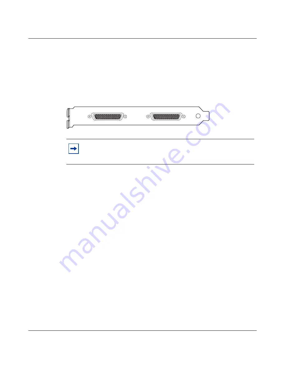
The dual V.35 WAN interface card has two DB26 connectors that provide the
signals needed to interface to V.35 equipment.
Figure 36
shows the dual V.35 WAN interface card.
Figure 36
Dual V.35 WAN interface card
You need a DSU/CSU (digital service unit/channel service unit) between the
WAN connection and the gateway. This section describes the connector and cables
used with V.35 WAN synchronous adapters.
If you build your own V.35 DTE cables, observe the following guidelines:
•
All connector hoods must be metal.
•
Braid must enter and make contact inside the metal connector hood.
•
V.35 conn strain relief must be conductive.
Included in the accessory box are two cables to attach to the V.35 connectors.
These cables enable the WAN adapter to function as DTE (data terminal
equipment).
Note:
The dual V.35 WAN interface card is no longer available for
purchase. Version 5.0 is the last release of Contivity software that will
support the dual V.35 WAN interface card.
CS260016A
Summary of Contents for 1700
Page 6: ...6 314711 D Rev 00 ...
Page 10: ...10 Contents 314711 D Rev 00 ...
Page 14: ...14 Tables 314711 D Rev 00 ...
Page 28: ...28 Chapter 1 Installing the Contivity 1700 chassis 314711 D Rev 00 ...
Page 42: ...42 Chapter 2 Cabling the gateway and turning the power on 314711 D Rev 00 ...
Page 50: ...50 Chapter 3 Configuring the management IP interface 314711 D Rev 00 Figure 16 Welcome screen ...
Page 52: ...52 Chapter 3 Configuring the management IP interface 314711 D Rev 00 ...
Page 88: ...88 Appendix A Technical specifications 314711 D Rev 00 ...
Page 94: ...94 Index 314711 D Rev 00 ...


