64
CONNECTION AND SETTINGS
:
Parameter Settings
z
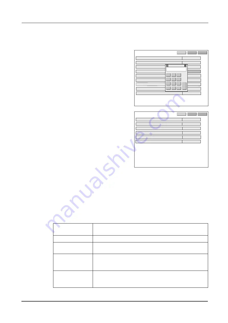
For the parameters whose settings must be specified by values, the numeric keypad is dis-
played.
1) Enter a value with the numeric keypad.
2) Press the Ent button to confirm the entry.
To cancel the entry, press the CE button.
3) The numeric keypad closes.
3
Press the >> button to go to the Parameter 2
screen and change the desired parameter set-
tings in the same manner.
4
Go back to the layout screen.
Press the EXIT button.
[Parameter description: Parameter 1 screen]
1) System: Blocker/LE, Mini LAB, Blocker LAB, VCA (Preset), VCA (Auto)
Factory setting: Blocker/LE
Sets the system configuration so that the ICE mini can be connected.
2CTCOGVGT
/KPK.#$
':+6
'0).+5*
56&
5[UVGO
45%$CWFTCVG
%WR/QFG
(WNNG[G/KPKOWO5K\G
)TKPF/KPKOWO5K\G*
)TKPF/KPKOWO5K\G8
)TQQXG&GRVJ
)TQQXG9KFVJ
.CPIWCIG
+%'OKPK㧦ޓ8غغޓޓ
'PV
%'
2CTCOGVGT
':+6
.'
6'0-';
.C[QWV2TGUGV
#NKIOGPV5ECNG2KVEJ
#NKIOGPV/CTM85K\G
2QNKUJ5$5GVVKPI
+PRWV+PVGTHCEG,1$260%QFG
&KURNC[CWVQQHHVKOGOKP
Blocker/LE
Smallest system comprised of the ICE mini directly connected to the LE-
9000SX (maximum of two units)
Mini LAB
Small- or middle-scale system where the ICE mini acts as a data server
Blocker LAB
System connecting the ICE mini and server PC via a LAN port.
The communication protocol is NIDEK-LAN.
VCA (Preset)
System using the RS-232cable via the Edger 1 port to connect the ICE
mini and Preset Initialization type VCA server PC.
The communication protocol is VCA.
VAC (Auto)
System using the RS-232cable via the Edger 1 port to connect the ICE
mini and Auto Initialization type VCA server PC.
The communication protocol is VCA.
Summary of Contents for ICE mini
Page 1: ...INTELLIGENT BLOCKER Model ICE mini OPERATOR S MANUAL...
Page 8: ...VI...
Page 24: ...14 BEFORE USE Labels Side and rear views...
Page 28: ...18 BEFORE USE Before First Use...
Page 72: ...62 MAINTENANCE List of Replacement Parts...
Page 90: ...80 SPECIFICATIONS AND ACCESSORIES Standard Configuration...
Page 92: ...82 INDEX X X inside value 7 Y Y inside value 7...
Page 93: ......


