


42
OPERATING PROCEDURES
:
Setting Processing Conditions and Entering Lens Layout Data
Minimum lens diameter for processing with the lens edger
Minimum lens diameter for processing with the ME-1000
{
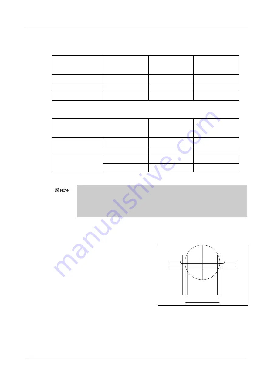
Setting WD
The WD represents the distance between the long-
est vertical lines in the middle on the left and right.
Enter the WD depending on the space between
the markings on the lens
.
It is also possible to set the WD just before
placing the lens on the lens table and block-
ing the lens.
Lens edger
Minimum lens
diameter for the
standard lens cup
Minimum horizontal
length for lens to be
processed
Minimum vertical
length for lens to be
processed
LE-9000 (Flat edging)
φ
28 mm
φ
21 mm
φ
19 mm
LE-9000 (Beveling)
φ
30 mm
φ
22 mm
φ
20 mm
SE-9090
φ
29 mm
φ
26 mm
φ
23 mm
Processing type
Minimum horizontal
length for lens to be
processed
Minimum vertical
length for lens to be
processed
Circumference processing
Grooving
Flat edging
φ
32 mm
φ
19 mm
Beveling
φ
33 mm
φ
20 mm
Safety beveling
Flat edging
φ
32 mm
φ
25 mm
Beveling
φ
34 mm
φ
26 mm
• When the lenses have an excessively short vertical diameter that the processing wheels
may come in contact with the lens cup, even when using a lens cup for half-eye lenses, the
yellow cup mark changes to red to warn the operator of a possibility of contact.
In such a case, change the layout mode to Passive and then block the lens. It is unnecessary to
change the lens layout data.
WD
Summary of Contents for ICE mini
Page 1: ...INTELLIGENT BLOCKER Model ICE mini OPERATOR S MANUAL...
Page 8: ...VI...
Page 24: ...14 BEFORE USE Labels Side and rear views...
Page 28: ...18 BEFORE USE Before First Use...
Page 72: ...62 MAINTENANCE List of Replacement Parts...
Page 90: ...80 SPECIFICATIONS AND ACCESSORIES Standard Configuration...
Page 92: ...82 INDEX X X inside value 7 Y Y inside value 7...
Page 93: ......


