Newton Security T-DAR T1000 Installation And Operation Manual Download Page 83


83 


I100 Door Position Encoder 

High resolution door position sensor provides digital-quadrature data to 
determine door position,with respect to the overhead stereo cameras. 
 
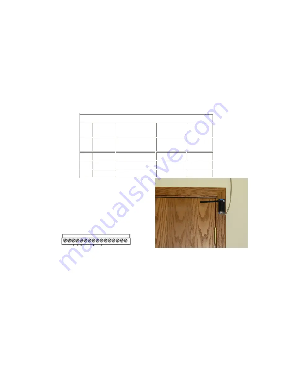
To install the Door Position Encoder use a straight thru Cat-5 with a RJ-45 
connector on one end and connect the lose wires on the other end to the 
Phoenix connector on the TDAR  Control Unit (as shown in the diagram 
below) using pins 13-16. If the Door Position Encoder is placed on Door 2 you 
must use Portal 2 Phoenix Connector.  


Pins                                 Portal 1 

13  Encoder 

Bl/Wh 

Blue CAT-5   

14  Encoder 

Gr/Wh 

Blue CAT-5   

15  Ground  Or,Or/Wh,Gr,Bl  Blue CAT-5 -Encoder 

16  +12 Volt  Br,Br/Wh 

Blue CAT-5 +Encoder 


Pin1                                                      Pin16 


Figure 36–pin out for encoder Cat-5               Figure 37 – Where to position Encoder on door 


Summary of Contents for T-DAR T1000

Page 1: ...000 and Model T2000 Single Door Two Door TAILGATING PIGGYBACKING DETECTION SYSTEM INSTALLATION AND OPERATION MANUAL Newton Security Inc 443 SW 41st Street Renton WA 98055 USA www newtonsecurityinc com...

Page 2: ...d with the data provided by the access device door contacts and other input data to determine if the tagged person is a legal transit or is tailgating piggybacking Once the status of a person is deter...

Page 3: ...ion switch signals must be immediate These signals must be sent to the T DAR unit at the same that the door is opened Unless it can be verified that the access control system can give immediate door o...

Page 4: ...ION 24 Important Safety and Warning Information 24 Tips for a Successful T DAR Installation 25 Physical Installation 26 Site Considerations 27 Before You Begin 28 Local Device Placement 28 Control Uni...

Page 5: ...vity 57 Cart Sensitivity 58 Crawler Sensitivity 58 Portal Selection 60 Door Control 61 Camera Geometry 62 Important Safety and Warning Information 65 Critical elements to maintain a properly operating...

Page 6: ...6 Connection details 81 T DAR Dual Digital Inputs 84 T DAR Digital Outputs 85 Known Issues and installation Tips 90 INDEX 91...

Page 7: ...from virtually any badge or pass system including biometrics and Smart ID systems When a violation occurs the alarm activates and the event camera records the violator in real time Data time and pass...

Page 8: ...tor External to the Elevator Door Systems Most Portals External to the Portal T DAR Models Not Covered In This Manual Double Door Systems Mantrap Systems Gate Turnstile Systems Outside Systems Vehicle...

Page 9: ...Complete T DAR System T2000 Complete Tailgate Detection System with CB200 Control Unit 2 DC 200LP Camera Heads and 2 S100 Annunciator Unites 3 1 Door Control Unit CB100 Single Door Control Unit 4 2 D...

Page 10: ...Head wall mounting bracket used for mounting a DC200LPLP to a flat wall 12 Thrown Object Detection Software F102 Option to detect thrown objects up to 60 Miles Per hour 13 Anti Pass Back Software F103...

Page 11: ...s available Storage Temperature 0 to 125 degrees Power Considerations The T DAR Systems requires relatively stable AC power If the system is installed in an area where the AC power is not stable and i...

Page 12: ...12 Figure 2 T DAR Control Unit CAD...

Page 13: ...panel tabs Standard Operating Temperature 40 to 125 degrees F optional high and low temperature systems available Storage Temperature 0 to 150 degrees F Input Voltage Current 12VDC 2A maximum Powered...

Page 14: ...14 Figure 4 T DAR Annunciator CAD...

Page 15: ...Storage Temperature 0 to 150 degrees F Input Voltage Current 12VDC 1A maximum Powered by the CB100 200 Control Unit Inputs 1 RJ45 Std Ethernet from Control Unit Outputs NTSC or PAL Stereo Video Speci...

Page 16: ...16 Figure 6 T DAR Stereo Tracking Head...

Page 17: ...les on back panel Optional mounting brackets available Standard Operating Temperature 40 to 125 degrees F optional high and low temperature systems available Storage Temperature 0 to 150 degrees F Inp...

Page 18: ...18 F igure 8 T DAR Door Encoder...

Page 19: ...F optional high and low temperature systems available Storage Temperature 0 to 125 degrees F Input Voltage Current 12VDC 24VAC 5A Inputs 12 DC or 24VAC Screw Terminals Note For 2 door systems event c...

Page 20: ...20 Figure 10 T DAR Event Camera...

Page 21: ...ance of 200 from the door to the CB100 200 Control Unit Input Voltage Current EA101 powered by the T DAR Control Unit no external power required EA101A supplied plug mounted power sulpply 115 230 VAC...

Page 22: ...22 Figure 12 T DAR Cable Extender Amplifier CAD...

Page 23: ...quire powered from the TDAR Control Unit Vs Ea101A W power adapter Use the EA101A for additional extenders for each 150 200 foot extension Power from a plug mounted power adapter supplied with the EA1...

Page 24: ...The T DAR system may contain produce and present the hazard for electrical shock or burns with the cover removed There are no user serviceable parts under the interior panels Only trained authorized...

Page 25: ...for this function that allows isolation from the access control system It is recommended that mechanical switches of the roller and plunger types be avoided in favor of magnetic switch door contacts...

Page 26: ...ent This allows the independent video signals to be synced Failure to have synced video signals will result in distorted and unusable event video replay clips Single door systems T 1000 may use DC dir...

Page 27: ...e lighting level is 300 Lux 30 Ft Candles from above The measurement should be taken so than only lighting emanating from above the ceiling in most cases is included in the measurement Lighting from t...

Page 28: ...munications and signals are not significantly diminished by voltage drop Adequate clearance should be maintained to the sides and bottom of the unit to facilitate the installation of conduit and venti...

Page 29: ...g System Visible or Near IR Order the correct head for the lighting at your installation Newton Security supplies Stereo Camera Heads for both types of lighting systems Distance from Stereo Camera Hea...

Page 30: ...camera head placement chart Failure to place the camera in the correct location will lead to false alarms or an altogether failure to detect violations The calculations in this chart are based upon d...

Page 31: ...a Head 09 20 23 51 107 2 71 DC 219 Stereo Camera Head 9 21 23 53 108 9 2 74 DC 225 Stereo Camera Head 9 21 23 53 114 2 95 DC 225 Stereo Camera Head 9 21 23 53 120 10 3 05 DC 225 Stereo Camera Head 12...

Page 32: ...head with BNC connectors Label the cables so that camera one is easily distinguished from camera two 2 Attach the coaxial cables to the upper panel Tracking Camera BNC inputs in accordance to the labe...

Page 33: ...ach the coaxial cables to the BNC 90 degree connectors on the inside of the stereo camera head The camera head can be opened by removing the screws in the access plate of the unit 5 Install and termin...

Page 34: ...r at all points of the arc that the door crosses and is required for doors that swing into the field of view of the tracking head This allows the T DAR to ignore the image signature of the door and fo...

Page 35: ...ystem performance There can be no noticeable latency in the receipt of valid access grant switch signals by T DAR 1 The valid access grant switch will connect to the Portal Digital Input terminal and...

Page 36: ...ays may be used to signal various alarm conditions based on user configurable options in the user interface All of these relays are single pole single throw and are normally open Various degrees of cu...

Page 37: ...37 Figure 16 Typical Dry Configuration...

Page 38: ...ction box labeled Use Following IP Address select this option 4 Enter the following information a IP 10 0 0 21 unless the unit is 21 then use 22 etc b Subnet 255 0 0 0 c Gateway 10 0 0 1 5 Apply these...

Page 39: ...ubstituting the s with the IP address of the vision system 7 Follow the on screen instructions After the software is loaded the UI may be launched from the start menu on the host computer Start Progra...

Page 40: ...p to step 7 4 Refer to Connect via Serial Ports to establish a serial port connection 5 Select Connection then Configure Connection from the application s menu bar 6 Select Ethernet IP address from th...

Page 41: ...Com1 Com2 ETC from the Configure Connection dialog box 14 Note You will need to make up a serial cable following the pin out shown below Serial Adaptor DB9 Female Color Phoenix 16 Pin 1 4 6 Jumper Not...

Page 42: ...arts and parcels should be removed before the calibration is performed This clean calibration will then allow the system to recognize objects introduced into the scene and track them accordingly while...

Page 43: ...AR Software Utilizing the T DAR user interface connect to the system to be configured and follow the steps as outlined below to configure the T DAR system for operation To conduct the set up operation...

Page 44: ...ntly After set up of Portal 1 change from Portal 1 to Portal 2 using the pull down box and repeat step 3 5 In the user interface change tabs to the Setup I O tab 6 Set the time and date on the control...

Page 45: ...O Setup View Installer I O Installer Camera Settings System Log and Advanced The User Interface Tab pages are navigated by a series of tabs and menus The tabs control the configuration setup and moni...

Page 46: ...d from this file Save Settings The Save Settings option compiles all the user configurable settings into a file to be saved for system back up This file has the nlc file extension This file should be...

Page 47: ...Choose the location of the desired file and click OK Exit Clicking the Exit button closes the User Interface The T DAR will continue to run and perform security inspections even with this interface di...

Page 48: ...d unit Disconnect From a connected or enabled User Interface Disconnect may be used to close the connection with the T DAR The ability to make changes to the unit ceases but the User Interface remains...

Page 49: ...The Set long and String properties allows you to manually enter values for properties which are not accessible with GUI Consult manufacturer for commands Clear property Cache This clears all long and...

Page 50: ...d gateway that you unit uses to connect to your company internal network Switch Setup The Switch Setup function is currently disabled Display Page Size The Display Screen size function shows screen re...

Page 51: ...not be able to move to any other tabs in the UI to complete the installation Figure 23 Initial Set Up Tab Camera set up Here the technician will input various distances that the cameras are place away...

Page 52: ...onfigurable items on this page Figure 24 Monitor Tab Display The Display section of this page controls which video displayed on the monitor The settings are unique to the portal being monitored the ou...

Page 53: ...s are available for changing the properties of the event camera view in the normal display mode These are as described below Full screen mode allows the user to select a full sized image for event vid...

Page 54: ...for before resetting Setting this value to zero causes the unit to be in manual reset mode only Below the Alarm Timeout is a Reset Alarm button that resets the T DAR alarm when clicked Policy The Allo...

Page 55: ...x allows the user to define a specific logical name to a door such as Door 569 North Entrance This name will be displayed in the event video playback loop Once a name has been entered here all of the...

Page 56: ...s viewed when the system process is stopped To stop the system process click on Run on the Menu bar at the top of the screen and select Stop Running This will make images available in the Viewing Wind...

Page 57: ...be loaded After the file is selected the controller will need to be restarted mains power interrupted to enable the new files Sensitivity The sensitivity section contains slider bars Detections level...

Page 58: ...be entered in the numeric box adjacent to each region Drawing a Box To draw a box in the Viewing Window the image displayed must be one of the two unwarped images An unwarped image is simply an image...

Page 59: ...accomplished by drawing a box for only one of the regions and then manually entering the numeric values identically in the other region The region should be all the way up the door wall the same as t...

Page 60: ...ges are password protected for Installer and System Administrators use only Portal Selection On multi door systems the selection and setup of the door being viewed is controlled by the combo box next...

Page 61: ...r If the door open count increments now then the switch is set incorrectly o If the count does not ever change switch the display mode to Show O and observe the display of the I O function on the scre...

Page 62: ...exists Likewise when Warnings set outputs check box 5 is clicked Portal 1 Relay Spare will close for that event Any combination of relays and triggering events may be selected There is no specificatio...

Page 63: ...63 System Log This tab allows you to see the activity of the system when doors open and close what alarms have been active and what inputs and outputs have been triggered Figure 30 System Log...

Page 64: ...at can override several of the standard controls of critical system functions detailed in previous tabs These items should only be adjusted at the direction of qualified Newton Security Personnel No A...

Page 65: ...The T DAR system may contain produce and present the hazard for electrical shock or burns with the cover removed There are no user serviceable parts under the interior panels Only trained authorized...

Page 66: ...to allow an entry and must have duration of at least 300 ms In some instances this may require the use of a timer module to allow for adequate lock activation time In all circumstances if a person cro...

Page 67: ...nt video signals to be synced Failure to have synced video signals will result in distorted and unusable event video replay clips Single door systems T 1000 may use DC direct current powered event cam...

Page 68: ...Green on Green off Door 1 is open Overtemp shutdown Normal Door 2 is open Temperature warning Normal 1 flash per access signal Normal 3 Alarm Red on Red flashing Red off Yellow on Yellow flashing Yel...

Page 69: ...the Voice Announcement via microphone b Gain access to the printed circuit board within the Annunciator Remove the 6 6 32 Phillips head screws that attach the top cover c Ensure that JP1 is set MIC JP...

Page 70: ...al off position i Replace and secure the cover with the 6 6 32 Phillips head screws Please see the figure on the following page for component locations Shown in default Microphone Programmable positio...

Page 71: ...hs to produce more accurate images Check with your Newton Security Inc Authorized Distributor regarding availability of Stereo Tracking Heads for special installations Lighting The minimum acceptable...

Page 72: ...Make sure you are using a crossover Ethernet cable Make sure your Laptop PC is set to 10 0 0 with a sub mask of 255 0 0 0 Try to connect using the COM port Ref to Pg 48 Turn off the computer restart...

Page 73: ...live image is entirely black then contact your Newton Security Inc Authorized Distributor Random Pixels Appear In The Image This is commonly caused by electrical noise generated by motors and controll...

Page 74: ...l light by moving the illumination source closer to the security area or by increasing the number of illumination sources Replace the Stereo Camera Head if problem persists The Image Is Too Bright Dec...

Page 75: ...source that has gone out completely can affect the performance Make sure that your light sources are strong and positioned correctly Good lighting is essential to getting a good image and to security...

Page 76: ...imum ON Current 10 mA Maximum OFF Current 0 1mA OFF to ON Response 0 2 mS Typical ON to OFF Response 0 2 mS Typical Common Single Common all 8 Channels DC Output Specifications Minimum Maximum Voltage...

Page 77: ...77 Lower Power Panel Connections Figure 35 Control Unit Connections Upper Front Panel Lower Power Panel Lower Front Panel...

Page 78: ...Interface Standard 10BaseT Cat 5 Ethernet cable to Stereo Camera Head Event Camera Input BNC connector from external Camera Head for Event Capture Video out Output BNC connector to security control m...

Page 79: ...2V Trigger on inputs Connect to 12V for Logic Low GND Trigger 12 Volt Output System 12V Ground Output System GND Rs232 TX Output serial data Rs232 RX Input serial data Input 3 Input door close sensor...

Page 80: ...s Connect to 12V for Logic Low GND Trigger Relay 6 A B Output general purpose Relay A B Pair closes connection on trigger Encoder A B Input quadrate data from door position sensor Lower Power Panel Co...

Page 81: ...table conditions Also the normal state of these relays is user definable to allow for greater flexibility in integrating the system with a variety of access control systems Two of the relays are locat...

Page 82: ...ss granted This is not necessary if a dedicated output is available from the access control system NOTE The power from the access control door lock should not be routed through the T DAR inputs Input...

Page 83: ...onnect the lose wires on the other end to the Phoenix connector on the TDAR Control Unit as shown in the diagram below using pins 13 16 If the Door Position Encoder is placed on Door 2 you must use Po...

Page 84: ...mon for the entire set of inputs all inputs must be configured as either sourcing or sinking It is not possible to mix the inputs between sourcing and sinking The following diagrams illustrate the typ...

Page 85: ...The T DAR uses relays for outputs When the relay is triggered connection points A B are closed and current is allowed to pass Applications should not exceed 3 amps The following diagram illustrates t...

Page 86: ...l tile ceiling Figure 1 Completed assembly Getting Started Refer to your T DAR installation and operation manual for recommended camera locations with respect to the entry door Check for obstructions...

Page 87: ...et cap screws You will also need Small handsaw Drill Phillips screwdriver 5 32 4mm hex key and a 1 16 hex key Panel Cutting Mark and cut a hole in the tile to match the layout dimensions The camera ce...

Page 88: ...d the upper plate to match the ceiling grid layout Align the upper plate and fixture hangers with the tile in place to get ready for the next step Final Assembly Start with the upper plate in the ceil...

Page 89: ...89...

Page 90: ...e to enter the fan intake of another T DAR Control Unit The return signal needs to be instant from the access control system for the TDAR to alarm properly Labeling the camera and Ethernet cables corr...

Page 91: ...Camera 78 Exit 47 File Menu 46 Fuses 76 Good Image 71 I100 9 Image Type 56 Initial Set Up 51 Input Impedance 76 Input Specifications 76 Installation 28 Installer Camera Settings 56 Installer I O 60 In...

Page 92: ...2 S100 9 Save Settings 46 Sensitivity 57 Serial Port 40 Serial Ports 41 Set Up I O 54 Sinking Inputs 84 Sinking Output 85 Site Considerations 27 Smart ID 7 Software 38 Sourcing Inputs 84 Storage Temp...

Reviews: