Trolley Return Unit 920/1500
17
EN
WARNING!
Risk of electric shock!
Work with electric equipment is to be carried out by a qualified electrician.
A lockable safety switch shall be installed between the system and the power
network.
5.2
Description of cable and end marking
Table 5-1: Cable and end marking
Circuit diagram marking interpretations
(1)SLX1 / X4:1
Designation.
(1)
Number on wires.
SLX1
Component designation that the wire is connected to.
/ X4
Terminal block that the wire is routed to.
:1
Terminal block number that an individual wire is connected to.
Wire colour marking
(1)BK
Designation.
(1)
Alternatively, the number on a wire if a numbered wire is used.
BK
Cable colour, black.
BN
Cable colour, brown.
BU
Cable colour, blue.
Cable marking
W1
Designation.
W
Designation for cables.
1
Cable number.
5.3
Installation of cables and connection boxes
Cable connection identification.
See Appendix A, Cable connections overview.
•
The wires in the cables W1 and W2 are marked with numbers.
•
The wires in the cables W3 to W8 are marked with colours.
Tools and materials
•
Stripping pliers (insulation on the wires must be stripped by 10 mm to ensure good
contact in the terminal blocks)
•
Cable cutters, knife, drill machine/automatic screwdriver
•
Instrument screwdriver, maximum 4 mm wide, to open the terminal blocks in
connection box 1 and 2.
•
Cable ties, fasteners.
•
Drill additional Ø 4.5 mm holes in exhaust rail for fasteners.
Transformer voltage setting and fuse
•
Remove the drive unit cover and check the transformer or wiring for correct
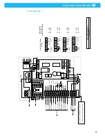
transformer voltage setting according to Appendix B, ‘Circuit diagram 1’.
•
Replace Fuse F1 if necessary according to Appendix A,
‘Cable connections overview’.
Identifying the circuit diagram
Check how many control boxes are supplied with the system, and depending on the
quantity, select the circuit diagram in question in accordance with the list below.
•
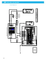
2 Control boxes, Standard, see Appendix B, ‘Circuit diagram 2’.
Summary of Contents for 920/1500
Page 2: ...Trolley Return Unit 920 1500 2 ...
Page 3: ...Trolley Return Unit 920 1500 3 English 4 ...
Page 28: ...Trolley Return Unit 920 1500 EN 28 Appendix A Cable connections Cable connections overview ...
Page 29: ...Trolley Return Unit 920 1500 29 EN Simple cable connections overview ...
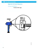
Page 30: ...Trolley Return Unit 920 1500 EN 30 Appendix B Circuit diagrams Driving slot circuit diagram ...
Page 31: ...Trolley Return Unit 920 1500 31 EN Circuit diagram 1 ...
Page 32: ...Trolley Return Unit 920 1500 EN 32 Circuit diagram 2 ...
Page 33: ...Trolley Return Unit 920 1500 33 EN Circuit diagram 3 ...
Page 34: ...Trolley Return Unit 920 1500 EN 34 Circuit diagram 4 ...
Page 35: ...Trolley Return Unit 920 1500 35 EN Circuit diagram 5 ...
Page 36: ...Trolley Return Unit 920 1500 EN 36 Circuit diagram 6 ...
Page 37: ...Trolley Return Unit 920 1500 37 EN Circuit diagram 7 ...
Page 38: ...Trolley Return Unit 920 1500 EN 38 Circuit diagram 8 ...
Page 39: ...Trolley Return Unit 920 1500 39 EN Circuit diagram 9 ...
Page 40: ...Trolley Return Unit 920 1500 EN 40 Circuit diagram 10 ...
Page 41: ......
Page 42: ......
Page 43: ......
Page 44: ...www nederman com ...


