Trolley Return Unit 920/1500
EN
16
32.
Fit connection box 2 on one of the rail’s mounting brackets closest to the
disconnection arrow, see Figure 15 and Figure 21.
33.
Fit the connection box so that its connections align in the rail’s longitudinal
direction.
34.
Fit the bus bar:
RH: Turn brackets 180° around screw ‘A’, see Figure 22 item ‘a’.
a)
Fit all brackets on the bus bar.
b)
Fit screw, washers and rhombic nut on the brackets.
c)
Fit the bus bar on the exhaust rail, see Figure 22 item ‘b’.
d)
Position the suction trolley against the suction trolley stop in the exit end of the
rail.
e)
Adapt the distance X3 so that the carbon brushes on the suction trolley driving
slot are still well in the bus bar, see Figure 22 item ‘c’.
f)
Adjust the position of the bus bar laterally by loosening the screws ‘A’. Make
sure that the carbon brushes are then in the correct position laterally against the
bus bar. Then tighten the screws ‘A’, see
Figure 22 item ‘a’.
35.
Determine a suitable location for the control boxes.
36.
Fit the control box (start/stop) on the wall close to the vehicle departure rail end, see
circuit diagrams 2 to 4. Assembly height from the floor is approximately 1.4 meters.
37.
Fit the control box (start/stop + manual/auto) on the wall near the vehicle arrival rail
end, see circuit diagrams 2 to 4. Assembly height from the floor is approximately 1.4
meters.
38.
Fit the motor damper in the channel between exhaust rail and fan.
39.
Do not connect Trolley Return Unit 920/1500 to the power network. Connect
the system components electrically in accordance with the circuit diagrams and
electrical installation instructions, see ‘Appendix A: Cable connections’.
Figure 21
Figure 22
Bus bar SLX3
Sheet for W3 connection
Screw, washers
and rhombic nut
A
X3
Vehicle travel direction
Sheet for
W3 connection
Bus bar SLX3
Carbon brushes
b
a
c
Summary of Contents for 920/1500
Page 2: ...Trolley Return Unit 920 1500 2 ...
Page 3: ...Trolley Return Unit 920 1500 3 English 4 ...
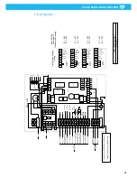
Page 28: ...Trolley Return Unit 920 1500 EN 28 Appendix A Cable connections Cable connections overview ...
Page 29: ...Trolley Return Unit 920 1500 29 EN Simple cable connections overview ...
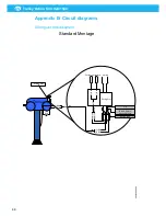
Page 30: ...Trolley Return Unit 920 1500 EN 30 Appendix B Circuit diagrams Driving slot circuit diagram ...
Page 31: ...Trolley Return Unit 920 1500 31 EN Circuit diagram 1 ...
Page 32: ...Trolley Return Unit 920 1500 EN 32 Circuit diagram 2 ...
Page 33: ...Trolley Return Unit 920 1500 33 EN Circuit diagram 3 ...
Page 34: ...Trolley Return Unit 920 1500 EN 34 Circuit diagram 4 ...
Page 35: ...Trolley Return Unit 920 1500 35 EN Circuit diagram 5 ...
Page 36: ...Trolley Return Unit 920 1500 EN 36 Circuit diagram 6 ...
Page 37: ...Trolley Return Unit 920 1500 37 EN Circuit diagram 7 ...
Page 38: ...Trolley Return Unit 920 1500 EN 38 Circuit diagram 8 ...
Page 39: ...Trolley Return Unit 920 1500 39 EN Circuit diagram 9 ...
Page 40: ...Trolley Return Unit 920 1500 EN 40 Circuit diagram 10 ...
Page 41: ......
Page 42: ......
Page 43: ......
Page 44: ...www nederman com ...


