Trolley Return Unit 920/1500
EN
18
•
3 Control boxes, Option 1 middle control box, see Appendix B, ‘Circuit diagram 3’.
•
3 Control boxes, Option 2 middle control box, see Appendix B, ‘Circuit diagram 4’,
which is used to complement an already installed system with an additional middle
control box.
Other information
Along with any of the above selected circuit diagrams, Appendix B, ‘Circuit diagram 1’
must always be used when connecting the suction trolley return unit.
Get a good idea of how the electrical system is designed by identifying the integral
electrical components in Appendix A, Cable connections overview where the cables are
identified by the designations W1–W16.
It is assumed that the connection boxes C_BOX_1 and C_BOX_2 and Drive unit are
fitted, and that disconnection arrow SLX1 has been positioned at the desired location in
consultation with the customer.
Bus bar SLX3 must be aligned so that the driving slot’s current collector has good
contact with the bottom of the bus bar and that the current collectors run without
resistance along the bus bar.
Check that the magnetic sensor SL2 is fitted about 0.7 metres in front of the disconnection
arrow SLX1.
WARNING!
Risk of electric shock!
The power supply must be disconnected from the drive unit. If the power supply cable is
already installed to the drive unit then the power supply must be disconnected from the
drive unit. Switch off the working switch and lock the knob with a padlock, and mark
this with the sign “Work in progress”.
Cable W2
1.
Route the cable W2 into connection box 1.
2.
Route the cable to the left in the connection box and connect it at the bottom of the
terminal block in accordance with Appendix B, ‘Circuit diagram 2’.
Cable W1
1.
Route the cable W1 into connection box 1 and connect in accordance with Appendix
B, ‘Circuit diagram 2’.
2.
Route the cable over the extraction channel.
3.
Drill a 4.5 mm hole in the top of the channel, press in a fastener and affix the cable.
4.
Route the cable through the fitting on the drive unit.
5.
Adapt the length of the cable so that the drive unit can be loosened and placed on top
of extraction channel during service.
6.
Connect the cable to the drive unit in accordance with Appendix B,
‘Circuit diagram 1’.
Cable W3
1.
Route the cable W3 into connection box 1 and connect in accordance with
Appendix B, ‘Circuit diagram 2’.
2.
Route the cable over the extraction channel and adjust the length of the cable
(maximum 1.5 m).
3.
Press the red flat pin sockets onto the wires and connect to SLX2 (bus bars’ rear
edge). Affix the cable with fasteners and cable ties.
Summary of Contents for 920/1500
Page 2: ...Trolley Return Unit 920 1500 2 ...
Page 3: ...Trolley Return Unit 920 1500 3 English 4 ...
Page 28: ...Trolley Return Unit 920 1500 EN 28 Appendix A Cable connections Cable connections overview ...
Page 29: ...Trolley Return Unit 920 1500 29 EN Simple cable connections overview ...
Page 30: ...Trolley Return Unit 920 1500 EN 30 Appendix B Circuit diagrams Driving slot circuit diagram ...
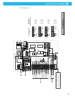
Page 31: ...Trolley Return Unit 920 1500 31 EN Circuit diagram 1 ...
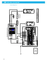
Page 32: ...Trolley Return Unit 920 1500 EN 32 Circuit diagram 2 ...
Page 33: ...Trolley Return Unit 920 1500 33 EN Circuit diagram 3 ...
Page 34: ...Trolley Return Unit 920 1500 EN 34 Circuit diagram 4 ...
Page 35: ...Trolley Return Unit 920 1500 35 EN Circuit diagram 5 ...
Page 36: ...Trolley Return Unit 920 1500 EN 36 Circuit diagram 6 ...
Page 37: ...Trolley Return Unit 920 1500 37 EN Circuit diagram 7 ...
Page 38: ...Trolley Return Unit 920 1500 EN 38 Circuit diagram 8 ...
Page 39: ...Trolley Return Unit 920 1500 39 EN Circuit diagram 9 ...
Page 40: ...Trolley Return Unit 920 1500 EN 40 Circuit diagram 10 ...
Page 41: ......
Page 42: ......
Page 43: ......
Page 44: ...www nederman com ...


