Trolley Return Unit 920/1500
25
EN
6
Work procedure (Normal operation)
1.
The vehicle drives into connection position.
2.
The exhaust hose is pulled down and the nozzle is connected onto the vehicle’s
exhaust pipe. Limit position SLX is opened: damper is opened and the fan is
activated. The suction trolley return runs from standby mode to active mode.
3.
The vehicle is driven forward and inspected along the extraction rail. The vehicle is
between the exhaust hose connection position and the exhaust hose disconnection
position.
4.
The vehicle has reached disconnection position and the hose is disconnected from
the exhaust pipe (manually or automatically). The balance block pulls up the hose
fully to the raised transport position.
Manual return: The return is activated with the start button.
Automatic return: The switch on Control box 2 must be in Auto position. When the
extraction hose is disconnected from the vehicle and is raised to transport position
the limit switch SLX is closed, which activates the trolley return sequence.
Return: When the return sequence is initiated the motor damper is activated and
starts closing the air flow in the extraction channel. The fan signal is disconnected
so that the fan is switched off and the wire drive motor starts at low speed to then
gradually increase to maximum speed. When the stop ball is captured by the driving
slot, the suction trolley return is started from the exhaust hose connection position to
the exhaust hose disconnection position.
5.
The suction trolley passes SL2 and the drive motor’s speed is reduced, the suction
trolley is parked in SLX1 “connection position” with reduced speed.
Reduction of the drive motor’s speed before connection position minimises back
swing of the exhaust hoses when the suction trolley is parked in connection position.
Disconnection arrow SLX1 opens the Driving slot springs on the driving slot, which
releases the suction trolley from the stop ball on the wire. The hose is in the raised
position and the suction trolley is in the connection position and the suction trolley
return system is then set in standby mode. The drive motor is still running after the
disconnection of the suction trolley. When the limit position SL4 on the Drive unit is
activated by the stop ball, the drive unit motor is stopped.
7
Malfunction (Drive unit motor moves the suc-
tion trolley)
Emergency stop
Activating an emergency stop immediately stops the Drive unit motor. To restart the
Drive unit motor the emergency stops must be reset. Restarting the Drive unit motor
takes place when the start button is depressed. The Drive unit motor starts with reduced
speed and increases gradually to maximum speed.
Overloading the Drive unit motor
If the Drive unit motor is overloaded, it will automatically activate the overload
protection and the Drive unit motor is stopped. Overload protection is engaged in 10
seconds and then you can manually restart the Drive unit motor with one of the start
buttons.
An internal counter keeps track of how many cases of overloading have occurred. If
the overload protection has been activated 3 times then you cannot restart with the start
button. In order to reset the overload counter you must activate and reset an emergency
stop, which then resets the counter.
Summary of Contents for 920/1500
Page 2: ...Trolley Return Unit 920 1500 2 ...
Page 3: ...Trolley Return Unit 920 1500 3 English 4 ...
Page 28: ...Trolley Return Unit 920 1500 EN 28 Appendix A Cable connections Cable connections overview ...
Page 29: ...Trolley Return Unit 920 1500 29 EN Simple cable connections overview ...
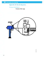
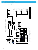
Page 30: ...Trolley Return Unit 920 1500 EN 30 Appendix B Circuit diagrams Driving slot circuit diagram ...
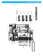
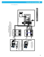
Page 31: ...Trolley Return Unit 920 1500 31 EN Circuit diagram 1 ...
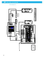
Page 32: ...Trolley Return Unit 920 1500 EN 32 Circuit diagram 2 ...
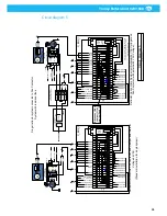
Page 33: ...Trolley Return Unit 920 1500 33 EN Circuit diagram 3 ...
Page 34: ...Trolley Return Unit 920 1500 EN 34 Circuit diagram 4 ...
Page 35: ...Trolley Return Unit 920 1500 35 EN Circuit diagram 5 ...
Page 36: ...Trolley Return Unit 920 1500 EN 36 Circuit diagram 6 ...
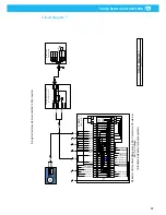
Page 37: ...Trolley Return Unit 920 1500 37 EN Circuit diagram 7 ...
Page 38: ...Trolley Return Unit 920 1500 EN 38 Circuit diagram 8 ...
Page 39: ...Trolley Return Unit 920 1500 39 EN Circuit diagram 9 ...
Page 40: ...Trolley Return Unit 920 1500 EN 40 Circuit diagram 10 ...
Page 41: ......
Page 42: ......
Page 43: ......
Page 44: ...www nederman com ...


