Trolley Return Unit 920/1500
19
EN
Cable W4
1.
Route the cable W4 (embedded cable from limit position SL4) under the extraction
channel behind the end stop into connection box 1 and connect in accordance with
Appendix B, ‘Circuit diagram 2’.
2.
Affix the cable with fasteners and cable ties.
Cable W2 continued
1.
Secure the cable W2 with a fastener on top of the extraction channel and press the
cable down into the extraction channel slot.
2.
Thread the cable cluster through the extraction channel’s mounting brackets and then
press the cable down into the extraction channel slot. Perform this the whole way up
to connection box 2.
3.
If the customer has ordered an additional control box, then an extra connection box
(Connection Box 3) is connected in a suitable location above the extraction channel,
see Appendix A, ‘Cable connections overview’, and connect in accordance with
Appendix B, ‘Circuit diagram 3’. A loop of cable can be temporarily routed where
the connection box should be located.
4.
Add a suitable surplus of cable in a loop above the extraction channel and connect
W2 in connection box 2.
Cable W5
1.
Route the cable W5 into connection box 2 and connect in accordance with
Appendix B, ‘Circuit diagram 2’.
2.
Route the cable over the extraction channel, maintain the cable’s length, 3 m, press
the red female pin sockets onto the wires and connect to SLX1 (disconnection
arrow’s rear edge).
3.
Affix the cable with fasteners and cable ties.
Cable W6
1.
Route the cable W6, embedded cable from limit position SL2 (Inductive sensor).
2.
Route the cable over the extraction channel. Maintain the length of the cable 3 m,
and route it into connection box 2 and connect in accordance with Appendix B,
‘Circuit diagram 2’.
3.
Affix the cable with fasteners and cable ties.
Cable W7 and W8
1.
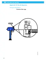
See Appendix B, ‘Driving slot circuit diagram’.
2.
Strip W7 and press flat pin sockets onto the blue and brown wires.
3.
Connect on the underside/rear edge of the current collectors.
4.
Adapt the limit position SLX cable W8 and cable W7 so that they reach up to the
lower edge of the driving slot.
5.
Add a suitable surplus for cable jointing and for future repairs.
6.
Cut off the wires that will not be used and thread the enclosed shrink tube over the
cables as illustrated.
7.
Strip the wires approximately. 15 mm.
8.
Join the brown/brown and blue/blue in 4 mm round female pin sockets.
9.
Press the sockets onto the driving slot’s pins. The positioning does not matter.
10.
Use fasteners to secure the cables on the suction trolley.
Summary of Contents for 920/1500
Page 2: ...Trolley Return Unit 920 1500 2 ...
Page 3: ...Trolley Return Unit 920 1500 3 English 4 ...
Page 28: ...Trolley Return Unit 920 1500 EN 28 Appendix A Cable connections Cable connections overview ...
Page 29: ...Trolley Return Unit 920 1500 29 EN Simple cable connections overview ...
Page 30: ...Trolley Return Unit 920 1500 EN 30 Appendix B Circuit diagrams Driving slot circuit diagram ...
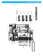
Page 31: ...Trolley Return Unit 920 1500 31 EN Circuit diagram 1 ...
Page 32: ...Trolley Return Unit 920 1500 EN 32 Circuit diagram 2 ...
Page 33: ...Trolley Return Unit 920 1500 33 EN Circuit diagram 3 ...
Page 34: ...Trolley Return Unit 920 1500 EN 34 Circuit diagram 4 ...
Page 35: ...Trolley Return Unit 920 1500 35 EN Circuit diagram 5 ...
Page 36: ...Trolley Return Unit 920 1500 EN 36 Circuit diagram 6 ...
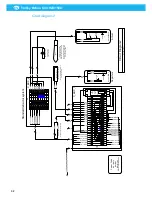
Page 37: ...Trolley Return Unit 920 1500 37 EN Circuit diagram 7 ...
Page 38: ...Trolley Return Unit 920 1500 EN 38 Circuit diagram 8 ...
Page 39: ...Trolley Return Unit 920 1500 39 EN Circuit diagram 9 ...
Page 40: ...Trolley Return Unit 920 1500 EN 40 Circuit diagram 10 ...
Page 41: ......
Page 42: ......
Page 43: ......
Page 44: ...www nederman com ...


