Trolley Return Unit 920/1500
EN
26
Another alternative is to switch off and switch on the power supply to the Drive unit.
Afterwards, you can restart the motor with one of the start buttons.
NOTE!
If the overload protection is activated when the suction trolley is connected to
the current collector SLX3, the overload protection is not reset until you have manually
moved the suction trolley away from the current collector or pulled down the hose so that
SLX is activated.
When the suction trolley is in disconnection position and the overload protection triggers,
it is likely that a mechanical fault has occurred. The operator must pay attention to any
faults in the driving slot/current collector.
The suction trolley jams in an object and the driving slot disengages from
the stop ball
If the hose/suction trolley jams for some reason then the driving slot will disengage from
the stop ball and the suction trolley return is interrupted. The drive motor will continue
to run until the stop ball reaches the limit position SL4 when the motor is stopped.
When you have rectified the problem that caused the disconnection you can restart the
drive motor with a start button. The driving slot is designed so that it can reconnect a
disconnected suction trolley on the stop ball.
NOTE!
Other malfunctions, see chapter ‘9 Troubleshooting’ or contact a service
technician.
8
Spare parts
Contact your nearest authorized distributor or Nederman for advice on technical service
or if you require help with spare parts. See also www.nederman.com.
Ordering spare parts
When ordering spare parts always state the following:
•
Part number and control number (see the product identification plate).
•
Detail number and name of the spare part (see www.nederman.com).
•
Quantity of the parts required.
Summary of Contents for 920/1500
Page 2: ...Trolley Return Unit 920 1500 2 ...
Page 3: ...Trolley Return Unit 920 1500 3 English 4 ...
Page 28: ...Trolley Return Unit 920 1500 EN 28 Appendix A Cable connections Cable connections overview ...
Page 29: ...Trolley Return Unit 920 1500 29 EN Simple cable connections overview ...
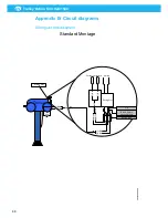
Page 30: ...Trolley Return Unit 920 1500 EN 30 Appendix B Circuit diagrams Driving slot circuit diagram ...
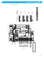
Page 31: ...Trolley Return Unit 920 1500 31 EN Circuit diagram 1 ...
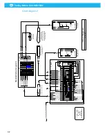
Page 32: ...Trolley Return Unit 920 1500 EN 32 Circuit diagram 2 ...
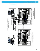
Page 33: ...Trolley Return Unit 920 1500 33 EN Circuit diagram 3 ...
Page 34: ...Trolley Return Unit 920 1500 EN 34 Circuit diagram 4 ...
Page 35: ...Trolley Return Unit 920 1500 35 EN Circuit diagram 5 ...
Page 36: ...Trolley Return Unit 920 1500 EN 36 Circuit diagram 6 ...
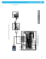
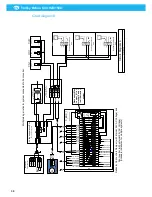
Page 37: ...Trolley Return Unit 920 1500 37 EN Circuit diagram 7 ...
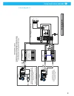
Page 38: ...Trolley Return Unit 920 1500 EN 38 Circuit diagram 8 ...
Page 39: ...Trolley Return Unit 920 1500 39 EN Circuit diagram 9 ...
Page 40: ...Trolley Return Unit 920 1500 EN 40 Circuit diagram 10 ...
Page 41: ......
Page 42: ......
Page 43: ......
Page 44: ...www nederman com ...


