Trolley Return Unit 920/1500
21
EN
5.4.1 Check cable W1
•
Check the connection at the Drive Unit terminal X2.
All of the wires on cable W1 are individually marked from 1 to 12 and shall be
connected to the corresponding number on the terminal X2: i.e. wire marked “1” is
connected to terminal X2:1 etc.
•
Check the connection at the Connection Box 1 / C_BOX_1 terminal X3.
In C_Box_1 you have to make sure that the wire 4 and 5 on cable W1 is connected
to terminal X3:14 and X3:15. All of the other wires shall be connected to their
corresponding terminal number.
5.4.2 Wiring tests
•
Move the suction trolley out of the Bus Bar or Disconnection Arrow.
•
Set the multimeter in Buzz test.
•
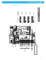
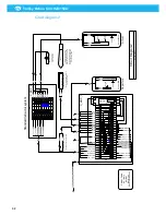
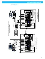
Open the C_Box_1. If not otherwise instructed, all continuous tests are performed in
C_BOX_1 terminal X3 (Circuit Diagrams 2, 3 and 4).
1.
Test the start button
1)
Make sure the trolley is not connected to the Bus Bar or the Disconnection
Arrow.
2)
Set Control Box 2 AUTO/MAN switch in manual mode.
3)
Place the black test probe in terminal 6.
4)
Place the red test probe in terminal 3.
5)
Press all start buttons one at a time.
If the wiring is installed according to the schematics the buzzer sounds when you press
the buttons.
2.
Test the Automatic/Manual switch.
1)
Place the black test probe in terminal 3.
2)
Place the red test probe in terminal 4.
3)
Set Control Box 2 AUTO/MAN switch in Auto mode.
If the wiring is installed according to the schematics the buzzer sounds when the switch
is in automatic mode.
3.
Test the Bus Bar (SLX3) connection
1)
Make sure the trolley is not connected to the Bus Bar or the Disconnection
Arrow.
2)
Set Control Box 2, AUTO/MAN switch in manual mode.
3)
Place the black test probe in terminal 6.
4)
Place the red test probe in terminal 4.
5)
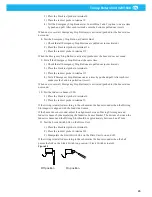
Connect a copper jumper between the Bus Bars both copper rails (see picture
below)
If the wiring is installed according to the schematics the buzzer sounds when the jumper
is connecting the Bus Bar copper rails.
Figure 23
W3
(1) BN
(2) BU
Bus Bar / SLX3
Jumper
Summary of Contents for 920/1500
Page 2: ...Trolley Return Unit 920 1500 2 ...
Page 3: ...Trolley Return Unit 920 1500 3 English 4 ...
Page 28: ...Trolley Return Unit 920 1500 EN 28 Appendix A Cable connections Cable connections overview ...
Page 29: ...Trolley Return Unit 920 1500 29 EN Simple cable connections overview ...
Page 30: ...Trolley Return Unit 920 1500 EN 30 Appendix B Circuit diagrams Driving slot circuit diagram ...
Page 31: ...Trolley Return Unit 920 1500 31 EN Circuit diagram 1 ...
Page 32: ...Trolley Return Unit 920 1500 EN 32 Circuit diagram 2 ...
Page 33: ...Trolley Return Unit 920 1500 33 EN Circuit diagram 3 ...
Page 34: ...Trolley Return Unit 920 1500 EN 34 Circuit diagram 4 ...
Page 35: ...Trolley Return Unit 920 1500 35 EN Circuit diagram 5 ...
Page 36: ...Trolley Return Unit 920 1500 EN 36 Circuit diagram 6 ...
Page 37: ...Trolley Return Unit 920 1500 37 EN Circuit diagram 7 ...
Page 38: ...Trolley Return Unit 920 1500 EN 38 Circuit diagram 8 ...
Page 39: ...Trolley Return Unit 920 1500 39 EN Circuit diagram 9 ...
Page 40: ...Trolley Return Unit 920 1500 EN 40 Circuit diagram 10 ...
Page 41: ......
Page 42: ......
Page 43: ......
Page 44: ...www nederman com ...


