Trolley Return Unit 920/1500
EN
14
26.
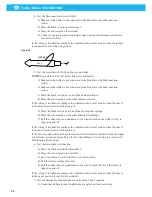
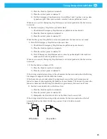
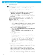
Fit the idler pulley unit in the rail as follows, see Figure 16:
a)
RH: Loosen the screws ‘a’, and turn the idler pulley 180°. Refit screws ‘a’ on the
other side.
b)
Slide in the idler pulley unit into the rail close to the disconnection arrow. Do not
tighten the idler pulley to the rail.
c)
Refit the rail connection sleeve.
27.
Fit the wire.
a)
Make a simple knot on the middle of the wire.
b)
Thread the wire around the idler pulley in the idler pulley unit. See Figure 17.
c)
Thread the lower part of the wire through the driving slot on the suction trolley,
see Figure 8 item ‘a’.
d)
Thread the upper wire around the drive unit drive pulley and idler pulleys, see
Figure 17 and Figure 19..
e)
Hang the upper wire over the guide pulley, see Figure 7. Pull and tighten the
wire so that it becomes adapted to the length of the rail.
f)
Make sure both loose ends of the wire are of equal length so that the connecting
knot is being placed symmetric to the first knot. Join the wire ends by the double
eight knot as shown in Figure 18.
·
Make an 8 on one wire end and let the other wire end follow the 8 backwards
·
Tighten carefully.
Figure 16
Idler pulley unit
a
Connection sleeve
Adjusting screw
Spring
Vehicle travel direction
Figure 17
Figure 18
Summary of Contents for 920/1500
Page 2: ...Trolley Return Unit 920 1500 2 ...
Page 3: ...Trolley Return Unit 920 1500 3 English 4 ...
Page 28: ...Trolley Return Unit 920 1500 EN 28 Appendix A Cable connections Cable connections overview ...
Page 29: ...Trolley Return Unit 920 1500 29 EN Simple cable connections overview ...
Page 30: ...Trolley Return Unit 920 1500 EN 30 Appendix B Circuit diagrams Driving slot circuit diagram ...
Page 31: ...Trolley Return Unit 920 1500 31 EN Circuit diagram 1 ...
Page 32: ...Trolley Return Unit 920 1500 EN 32 Circuit diagram 2 ...
Page 33: ...Trolley Return Unit 920 1500 33 EN Circuit diagram 3 ...
Page 34: ...Trolley Return Unit 920 1500 EN 34 Circuit diagram 4 ...
Page 35: ...Trolley Return Unit 920 1500 35 EN Circuit diagram 5 ...
Page 36: ...Trolley Return Unit 920 1500 EN 36 Circuit diagram 6 ...
Page 37: ...Trolley Return Unit 920 1500 37 EN Circuit diagram 7 ...
Page 38: ...Trolley Return Unit 920 1500 EN 38 Circuit diagram 8 ...
Page 39: ...Trolley Return Unit 920 1500 39 EN Circuit diagram 9 ...
Page 40: ...Trolley Return Unit 920 1500 EN 40 Circuit diagram 10 ...
Page 41: ......
Page 42: ......
Page 43: ......
Page 44: ...www nederman com ...


