Trolley Return Unit 920/1500
23
EN
2)
Place the black test probe in terminal 6.
3)
Place the red test probe in terminal 5.
4)
Test the Emergency Stop Button(s) at Control Box 2 and 3 (option) one at a time
by push and pull. After each test make sure the button is pulled out (reset).
When one (or several) Emergency Stop Button(s) is activated (pushed in) the buzzer does
not sound.
8.
Test the Emergency Stop Button at Control Box 1.
1)
Check that all Emergency Stop Buttons are pulled out (not activated).
2)
Place the black test probe in terminal 16.
3)
Place the red test probe in terminal 15.
When the Emergency Stop Button is activated (pushed in) the buzzer does not sound.
9.
Test all the Emergency Stop Button at the same time.
1)
Check that all Emergency Stop Buttons are pulled out (not activated).
2)
Place the black test probe in terminal 6.
3)
Place the red test probe in terminal 15.
4)
Test all Emergency Stop Buttons one at a time by push and pull. After each test
make sure the button is pulled out (reset).
When one (or several) Emergency Stop Button(s) is activated (pushed in) the buzzer does
not sound.
10.
Test the Inductive Sensor (SL2).
1)
Place the black test probe in terminal 6.
2)
Place the red test probe in terminal 2.
If the wiring is installed according to the schematics the buzzer sounds when the Driving
Slot magnet is aligned with the Inductive Sensor.
If the buzzer does not sound, adjust the alignment between Driving Slot magnet and
Inductive Sensor by manipulating the Inductive Sensor bracket. The distance between the
Inductive Sensor and the Driving Slot should be approximately between 4 and 7 mm
11.
Test the Limit Switch SL4 on the Drive Unit.
1)
Place the black test probe in terminal 6.
2)
Place the red test probe in terminal 14.
3)
Manipulate the Limit Switch SL4 on the Drive Unit to on and off.
If the wiring is installed according to the schematics the buzzer sounds when the ball
passes the fork on the Limit Switch (on position = Limit Switch actuated).
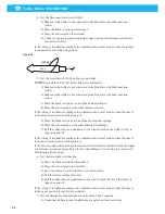
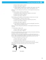
Figure 25
Off position
On position
Summary of Contents for 920/1500
Page 2: ...Trolley Return Unit 920 1500 2 ...
Page 3: ...Trolley Return Unit 920 1500 3 English 4 ...
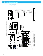
Page 28: ...Trolley Return Unit 920 1500 EN 28 Appendix A Cable connections Cable connections overview ...
Page 29: ...Trolley Return Unit 920 1500 29 EN Simple cable connections overview ...
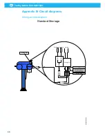
Page 30: ...Trolley Return Unit 920 1500 EN 30 Appendix B Circuit diagrams Driving slot circuit diagram ...
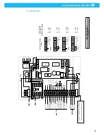
Page 31: ...Trolley Return Unit 920 1500 31 EN Circuit diagram 1 ...
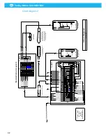
Page 32: ...Trolley Return Unit 920 1500 EN 32 Circuit diagram 2 ...
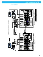
Page 33: ...Trolley Return Unit 920 1500 33 EN Circuit diagram 3 ...
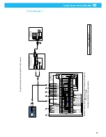
Page 34: ...Trolley Return Unit 920 1500 EN 34 Circuit diagram 4 ...
Page 35: ...Trolley Return Unit 920 1500 35 EN Circuit diagram 5 ...
Page 36: ...Trolley Return Unit 920 1500 EN 36 Circuit diagram 6 ...
Page 37: ...Trolley Return Unit 920 1500 37 EN Circuit diagram 7 ...
Page 38: ...Trolley Return Unit 920 1500 EN 38 Circuit diagram 8 ...
Page 39: ...Trolley Return Unit 920 1500 39 EN Circuit diagram 9 ...
Page 40: ...Trolley Return Unit 920 1500 EN 40 Circuit diagram 10 ...
Page 41: ......
Page 42: ......
Page 43: ......
Page 44: ...www nederman com ...


