Trolley Return Unit 920/1500
9
EN
installed on the other side. Allow for installation dimensions from the rail profile’s centre,
horizontally in each direction, of at least 400 mm.
NOTE!
This installation instruction describes a LH installation and that there are
special notes for a RH installation, marked as ‘RH’, when modification of components is
required. All components included in the return unit are factory assembled for fitting on
the LH side of the rail.
Follow the steps below to assemble the Trolley Return Unit 920/1500:
1.
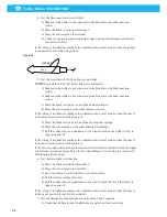
Remove the suction trolley stop from the rail, see ‘Figure 3’.
a)
Drill holes for the motor unit brackets as illustrated.
RH: Drill holes on other side of suction trolley stop.
b)
Fit and secure the Drive unit brackets on the suction trolley stop.
RH: Fit the supplied rubber stop extension according to ‘Figure 3’.
2.
Fit and secure connection box 1 on the other side of the suction trolley stop, see
Figure 4. Use the supplied self-drilling and self-tapping screws.
3.
Fit the suction trolley stop with connection box 1 on the suction rail, see Figure 5.
4.
Fit and secure the drive unit in the brackets.
Figure 3
170 35
Rubber stop extension (RH)
130 24
Ø 6.5
Suction trolley stop
Vehicle travel direction
Figure 4
Self drilling and tapping screws
Figure 5
Summary of Contents for 920/1500
Page 2: ...Trolley Return Unit 920 1500 2 ...
Page 3: ...Trolley Return Unit 920 1500 3 English 4 ...
Page 28: ...Trolley Return Unit 920 1500 EN 28 Appendix A Cable connections Cable connections overview ...
Page 29: ...Trolley Return Unit 920 1500 29 EN Simple cable connections overview ...
Page 30: ...Trolley Return Unit 920 1500 EN 30 Appendix B Circuit diagrams Driving slot circuit diagram ...
Page 31: ...Trolley Return Unit 920 1500 31 EN Circuit diagram 1 ...
Page 32: ...Trolley Return Unit 920 1500 EN 32 Circuit diagram 2 ...
Page 33: ...Trolley Return Unit 920 1500 33 EN Circuit diagram 3 ...
Page 34: ...Trolley Return Unit 920 1500 EN 34 Circuit diagram 4 ...
Page 35: ...Trolley Return Unit 920 1500 35 EN Circuit diagram 5 ...
Page 36: ...Trolley Return Unit 920 1500 EN 36 Circuit diagram 6 ...
Page 37: ...Trolley Return Unit 920 1500 37 EN Circuit diagram 7 ...
Page 38: ...Trolley Return Unit 920 1500 EN 38 Circuit diagram 8 ...
Page 39: ...Trolley Return Unit 920 1500 39 EN Circuit diagram 9 ...
Page 40: ...Trolley Return Unit 920 1500 EN 40 Circuit diagram 10 ...
Page 41: ......
Page 42: ......
Page 43: ......
Page 44: ...www nederman com ...


