Trolley Return Unit 920/1500
15
EN
a
b
g)
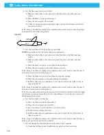
While the idler pulley unit is not fixed to the rail, push the idler pulley unit as far
as possible towards the end of the rail and fix the idler pulley unit to the rail.
28.
Tighten the wire further by adjusting the screw and nuts on the end of the idler
pulley unit until the spring is compressed to a 50 mm (2’’) length, see Figure 16.
29.
Check the wire tension, see also Section ‘5.5 Installation checking’.
30.
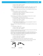
Check that the wire is running in the centre of the driving slot spring fork (on the
suction trolley). Adjustments can be made by laterally pressing the idler pulley unit
panel slightly. See Figure 19.
31.
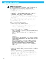
Mount the supplied stop balls on the wire directly before each knot (with regard to
wire travel direction). See Figure 20 item ‘a’.
NOTE!
The hexagon socket screw must be tightened against the wire protection
sheet according to the picture. See Figure 20 item ‘b’.
Figure 19
Figure 20
Wire protection sheet
Vehicle departure
Vehicle arrival
Vehicle arrval
Vehicle departure
LH wire travel direction
RH wire travel direction
LH installation
RH installation
Summary of Contents for 920/1500
Page 2: ...Trolley Return Unit 920 1500 2 ...
Page 3: ...Trolley Return Unit 920 1500 3 English 4 ...
Page 28: ...Trolley Return Unit 920 1500 EN 28 Appendix A Cable connections Cable connections overview ...
Page 29: ...Trolley Return Unit 920 1500 29 EN Simple cable connections overview ...
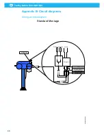
Page 30: ...Trolley Return Unit 920 1500 EN 30 Appendix B Circuit diagrams Driving slot circuit diagram ...
Page 31: ...Trolley Return Unit 920 1500 31 EN Circuit diagram 1 ...
Page 32: ...Trolley Return Unit 920 1500 EN 32 Circuit diagram 2 ...
Page 33: ...Trolley Return Unit 920 1500 33 EN Circuit diagram 3 ...
Page 34: ...Trolley Return Unit 920 1500 EN 34 Circuit diagram 4 ...
Page 35: ...Trolley Return Unit 920 1500 35 EN Circuit diagram 5 ...
Page 36: ...Trolley Return Unit 920 1500 EN 36 Circuit diagram 6 ...
Page 37: ...Trolley Return Unit 920 1500 37 EN Circuit diagram 7 ...
Page 38: ...Trolley Return Unit 920 1500 EN 38 Circuit diagram 8 ...
Page 39: ...Trolley Return Unit 920 1500 39 EN Circuit diagram 9 ...
Page 40: ...Trolley Return Unit 920 1500 EN 40 Circuit diagram 10 ...
Page 41: ......
Page 42: ......
Page 43: ......
Page 44: ...www nederman com ...


