Trolley Return Unit 920/1500
11
EN
10.
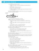
Fit the fixed limit switch SLX on the suction trolley, see Figure 9.
11.
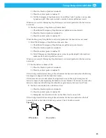
Engage the balance block catch, see Figure 10.
a)
The balance block catch is engaged in position ‘A’.
b)
The balance block catch is disengaged in position ‘B’.
12.
Pull out the balance block wire and ensure that the catch is locked, see Figure 10
item ‘a’.
13.
Loosen the balance block wire from the exhaust hose mounting.
14.
Remove the existing control ball, spring and wire stop from the balance block wire.
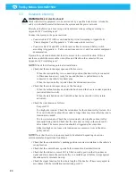
Thread the balance block wire through the limit switch ‘SLX ring’ and through
the supplied plastic limit switch actuator with spring and through the wire stop in
accordance with Figure 9 and Figure 11 item ‘a’, ‘b’ and ‘c’.
Figure 9
Limit switch SLX
Figure 10
B
A
Summary of Contents for 920/1500
Page 2: ...Trolley Return Unit 920 1500 2 ...
Page 3: ...Trolley Return Unit 920 1500 3 English 4 ...
Page 28: ...Trolley Return Unit 920 1500 EN 28 Appendix A Cable connections Cable connections overview ...
Page 29: ...Trolley Return Unit 920 1500 29 EN Simple cable connections overview ...
Page 30: ...Trolley Return Unit 920 1500 EN 30 Appendix B Circuit diagrams Driving slot circuit diagram ...
Page 31: ...Trolley Return Unit 920 1500 31 EN Circuit diagram 1 ...
Page 32: ...Trolley Return Unit 920 1500 EN 32 Circuit diagram 2 ...
Page 33: ...Trolley Return Unit 920 1500 33 EN Circuit diagram 3 ...
Page 34: ...Trolley Return Unit 920 1500 EN 34 Circuit diagram 4 ...
Page 35: ...Trolley Return Unit 920 1500 35 EN Circuit diagram 5 ...
Page 36: ...Trolley Return Unit 920 1500 EN 36 Circuit diagram 6 ...
Page 37: ...Trolley Return Unit 920 1500 37 EN Circuit diagram 7 ...
Page 38: ...Trolley Return Unit 920 1500 EN 38 Circuit diagram 8 ...
Page 39: ...Trolley Return Unit 920 1500 39 EN Circuit diagram 9 ...
Page 40: ...Trolley Return Unit 920 1500 EN 40 Circuit diagram 10 ...
Page 41: ......
Page 42: ......
Page 43: ......
Page 44: ...www nederman com ...


