background image

NX15/NX25 Operations and Maintenance Manual

Operating the transmitter

Issue 6.0  2019-01-31

Page 2-117

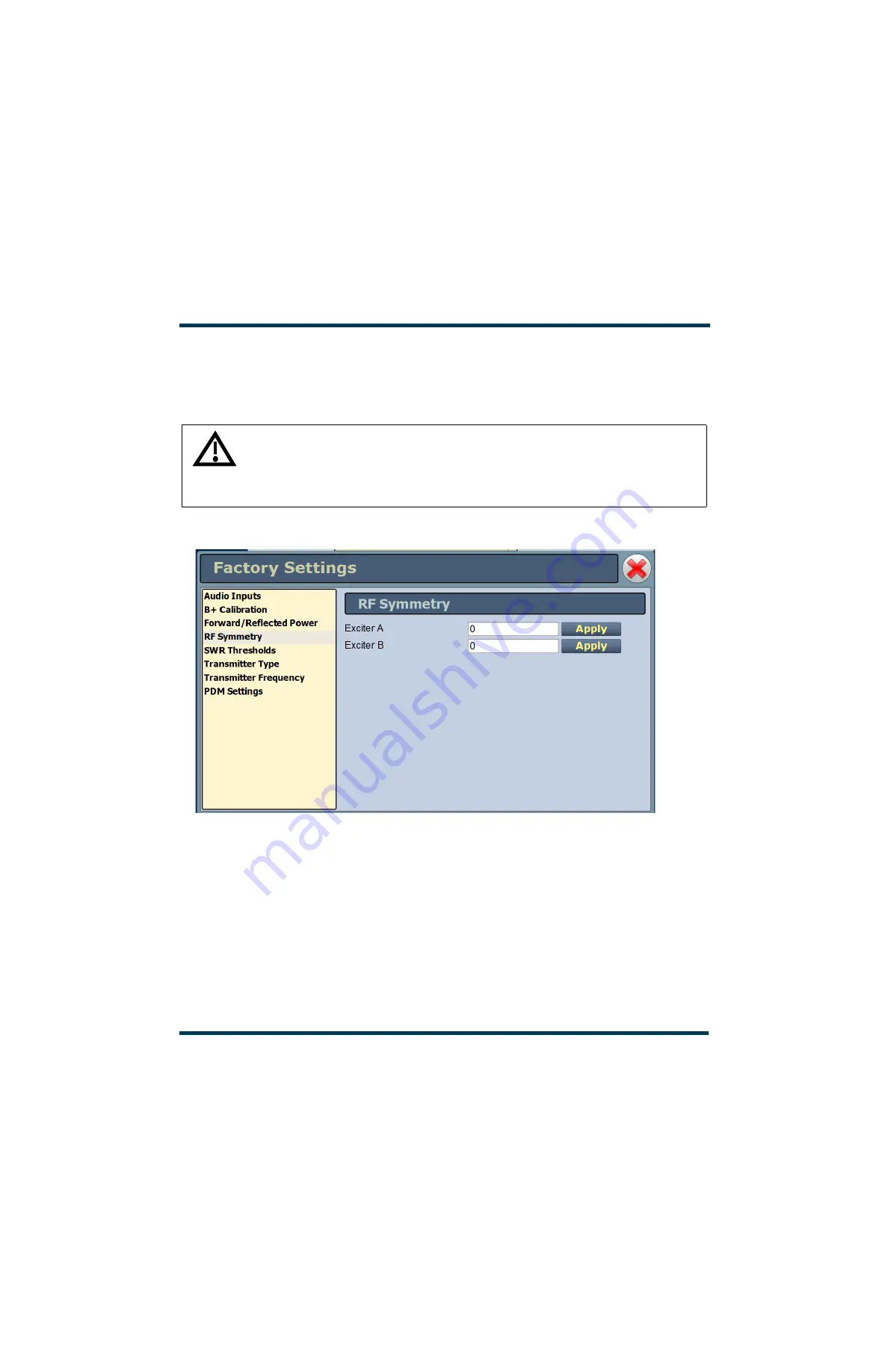
RF Symmetry

The 

RF Symmetry 

page (see 

Figure 2.88

) allows entering RF symmetry values for exciter A or 

B to attempt to minimize second harmonic content when operating on each exciter. Values are 

factory set and should not require adjustment.

Figure 2.88: Factory Settings - RF Symmetry

WARNING: Factory settings are established at the factory and should not require any adjustment. 
These settings affect critical system protections. Making changes to these settings may void your 
warranty. Contact Nautel before making changes.

For future reference, record a parameter value before and after making a change.

Summary of Contents for NX15

Page 1: ...NX15 NX25 Transmitter Operations and Maintenance Manual Document NHB NX15 NX25 OPS Issue 6 0 2019 01 31 Status Standard...

Page 2: ......

Page 3: ...Fax 1 207 947 3693 Customer Service 24 hour support 1 877 628 8353 Canada USA only 1 902 823 5100 International Email support nautel com Web www nautel com The comparisons and other information provi...

Page 4: ......

Page 5: ...enu page describing transmitter operations 2 20 Viewing Transmitter Log 2 22 Instrument Panels viewing displays 2 29 Meters page viewing real time meters 2 45 Presets editing operational settings 2 51...

Page 6: ...2 138 Routine maintenance 3 1 Scheduled maintenance 3 1 Replacing the air filter 3 2 Performing on air checks 3 4 Replacing the Control Interface PWB battery 3 6 Inspecting lightning protection syste...

Page 7: ...NX15 NX25 Operations and Maintenance Manual Issue 6 0 2019 01 31 Page vii Release control record Issue Date Reason 6 0 2019 04 01 Supports hardware NARA59D and software version NX SW 4 7 or higher...

Page 8: ...NX15 NX25 Operations and Maintenance Manual Page viii Issue 6 0 2019 01 31...

Page 9: ...1 4 Control Monitor Stage see page 1 7 RF Power Stage see page 1 8 RF Output Network see page 1 9 includes combiner and filter Refer to the functional block diagram see Figure 1 6 on page 1 15 NX15 NX...

Page 10: ...ies a B current sample to the rack interface PWB The rectifier assembly output is applied to a choke input filter and the B distribution assembly which then provide the B voltage to the RF power modul...

Page 11: ...the B current sample and provides this information along with data received over a serial bus from the RF power modules to the transmitter controller Monitors the arc detector assembly Generates the...

Page 12: ...d generate fully digital RF drive and interphase PDM drive signals for the power amplifiers and modulators in the RF power modules Audio signals for analog AM modulation can be applied as balanced ana...

Page 13: ...tion circuit adjusts the PDM duty cycle to compensate for variations in the B supply in order to maintain constant transmitter output power and minimize hum A PDM inhibit A or B input is applied from...

Page 14: ...ult conditions Provides a PM Enable signal for the RF power modules to monitor the PDM cable status This signal is held low 0 V by the exciter Provides real time telemetry of exciter samples over a st...

Page 15: ...to generate on board power supply requirements Monitors the forward and reflected power samples from the directional coupler and initiates a shutback when the reflected power exceeds the factory set...

Page 16: ...W RF power blocks The NX15 NX25 contains 5 RF power blocks Each RF power block contains two RF power modules and associated relays a fan tray and connections to the RF drive distribution PWB PDM distr...

Page 17: ...ing purposes see VSWR Protection on page 1 10 A static drain choke provides a dc short to ground to dissipate static build up on the antenna system and an adjustable spark gap provides protection for...

Page 18: ...protection circuit is set for a peak reflected power equivalent to 1 5 1 at 15 kW NX15 or 25 kW NX25 plus 100 peak modulation using the reflected power sample from the directional coupler see Figure 1...

Page 19: ...0 W and remains in that state for 100 ms This allows time for an arc or tran sient fault to clear After 100 ms the output power exponentially ramps up to the power set point or the power limit set by...

Page 20: ...f full carrier power Further cutbacks will not decrease the power beyond this point When the transmitter is recovering from a cutback event the accumulator must first reach 0 which takes 60 s After th...

Page 21: ...d in order to maintain a reflected power that is less than this limit This gradual reduction in power into high VSWR allows the transmitter to continue to operate into VSWR levels as high as 1 5 1 at...

Page 22: ...NX15 NX25 Operations and Maintenance Manual Description Page 1 14 Issue 6 0 2019 01 31...

Page 23: ...NX15 NX25 Operations and Maintenance Manual Issue 6 0 2019 01 31 Page 1 11 Figure 1 6 NX Series Transmitter Block Diagram...

Page 24: ...NX15 NX25 Operations and Maintenance Manual Page 1 12 Issue 6 0 2019 01 31 This page left bla...

Page 25: ...age 2 22 Instrument Panels viewing displays see page 2 29 Meters page viewing real time meters see page 2 44 Presets editing operational settings see page 2 50 Preset Scheduler see page 2 65 Status vi...

Page 26: ...owser This section includes the following topics Logging into the AUI on page 2 3 Describing the AUI layout on page 2 9 Navigating from page to page on page 2 12 Summarizing the AUI pages on page 2 13...

Page 27: ...settings See Precorrection Settings page on page 104 User Accounts See User Accounts on page 72 Changeover See Changeover page changing exciter transfer settings on page 113 User settings See User Set...

Page 28: ...ately 14MB Therefore if the connection speed to the transmitter is 1Mb s it will take approximately 2 minutes for the login screen to load 5 Log in to the AUI by entering the appropriate parameters in...

Page 29: ...r Settings see page 2 77 Network Setup Email Configuration Notifications Exgine Settings SNMP Configuration Audio Loss Power Thresholds Remote I O see page 2 123 Inputs Outputs Status see page 2 70 Lo...

Page 30: ......

Page 31: ...nsmitter is on or apply ac power to the transmitter 2 If the Local Autologin feature is properly configured see User Accounts on page 2 72 the AUI Home page will display without a login requirement 3...

Page 32: ...time Press Menu User Settings to access the Time Setup page to edit the time and date See Time Setup on page 89 Scheduler Displays the on off status of the Scheduler Press the Scheduler button upper p...

Page 33: ...includes the following buttons some of which open other menus and displays RF On Press to enable the transmitter s RF power stage RF Off Press to disable the transmitter s RF power stage Menu Press t...

Page 34: ...ll remote control functions same as local AUI Only the following remote AUI functionality is available when remote control is disabled All other functionality is unavailable remotely Full viewing acce...

Page 35: ...UI screen by pressing the logo upper left corner or by selecting Menu Home The Menu page is accessed from the bottom panel by pressing Menu Figure 2 5 Home page and Menu page selection items HOME PAGE...

Page 36: ...Page Home first page available via local or remote operation Displays an overview of transmitter features including various meters and instrument panels Choose options and navigate to other pages page...

Page 37: ...e operation Choose the instrument panel option s 16 options are available Up to four screens can appear on one page page 2 29 System Review Meters available via local or remote operation Choose meters...

Page 38: ...local operation or remote operation Create and edit scheduler rules page 2 65 Transmitter Status available via local or remote operation View transmitter s active faults page 2 70 User Accounts avail...

Page 39: ...e SNMP information capture critical parameters set time and date enable configure NTP servers and set call sign ID page 2 77 System Settings available via local or remote operation Screen configuratio...

Page 40: ...the Precorrection page page 2 104 Changeovers available via local or remote operation Set the main exciter and auto changeover functions page 2 113 Factory Settings available via local or remote opera...

Page 41: ...erations and Maintenance Manual Operating the transmitter Issue 6 0 2019 01 31 Page 2 17 Audio Player available via local or remote operation Manage the audio playlist files page 2 128 AUI Page Functi...

Page 42: ...first screen to appear after you log into the AUI It contains the images that were last viewed in the AUI from the previous login session You can return to the Home page from any screen by pressing th...

Page 43: ...elect the following operations Press Home to return to the home page See Home page describing the first page on page 19 Press Presets to open screens related to presets See Presets editing operational...

Page 44: ...e Changeover page changing exciter trans fer settings on page 113 Press User Settings to access a page that allows network configuration email configu ration and alarm notifications setting of Exgine...

Page 45: ...g Manager screen see Managing the Log on page 2 23 the events displayed may be filtered by the originating device Controller Exciter Rack or PM power module and the time of occurrence A maximum of fiv...

Page 46: ...display indicate specific information about the event Device indicates the origin device of the event Controller Exciter Rack RF Module etc Event indicates the event name State indicates whether the...

Page 47: ...cable exciter events only Rack displays applicable Rack events only PM displays applicable power module events only Click the Select All radio button default to show all of the most recent events for...

Page 48: ...f all the logs in the selected list copied to the remote user s computer clipboard by clicking on the Copy Logs button in the log manager see Figure 2 10 You can paste the tab delimited text copy of t...

Page 49: ...11 on page 2 26 Click the Delete All checkbox and click OK to delete all events Click the Delete by date checkbox to allow deletion of events that occurred prior to Older than a user specified date an...

Page 50: ...indicate specific information about the events Device refers to the device that is associated with the alarm The device options are Controller Exciter Rack and PM power module Event describes the alar...

Page 51: ...2019 01 31 Page 2 27 Legend Click on the Legend button in the Log Manager see Figure 2 13 to display a legend that describes the meaning of the symbols shown in the State and Severity columns of the...

Page 52: ...nels to display from 12 possible information panels Figure 2 14 Figure 2 14 Instrument Panel Options To view the instrument panel options close an existing panel by pressing X upper right corner and t...

Page 53: ...ase signal page 2 37 Signal Constellation For IBOC mode only Displays the phase and amplitude of the symbols being modulated within an OFDM sub carrier as dots on a cartesian graph Also displays timin...

Page 54: ...B DRM and DRM AM standards ITU R SM 328 11 and ITU R SM 1541 4 IBOC and IBOC AM NRSC 5 C NOTE Any spurious emissions that are displayed are a product of the spectrum analyzer and are not actually pre...

Page 55: ...ault is 300 Hz Decreasing this value provides better frequency resolution but will increase the sweep time Span determines the start and stop frequencies of the analyzer with the carrier fre quency al...

Page 56: ...n are relative to the channel frequency Figure 2 17 EQ Frequency Response EQ frequency response See Figure 2 17 This panel displays the frequency response of the active exciter s EQ filter Displays th...

Page 57: ...el displays the impulse response of the modulator s EQ filter Touch on the panel to display a cursor in the approximate area The cursor position filter tap and magnitude is noted in the upper right ha...

Page 58: ...ts bandwidth Touch on the panel to display a cursor in the approximate area The cursor position frequency and delay is noted in the upper right hand corner of the panel Touch in other areas of the too...

Page 59: ...anel displays the amplitude correction being applied to the magnitude signal The x axis represents the signal amplitude and the y axis represents the gain correction applied for a given amplitude valu...

Page 60: ...resents the phase shift correction applied for a given amplitude value Touch on the panel to display a cursor in the approximate area The cursor position LUT index and phase is noted in the upper righ...

Page 61: ...l data points Sub carrier group information is shown in the lower right section of the screen Displayed information includes the sub carrier group name the bandwidth that the selected carrier group oc...

Page 62: ...ting in stereo mode or not operating digital Left and right audio content is displayed for all other audio sources The plot consists of a group of sequential samples to allow signal analysis In L and...

Page 63: ...j0 ohms which implies a perfect 50 ohm load is being applied to the output of the transmitter Touch on the panel to display a cursor in the nearest area on the trace showing the normalized impedance...

Page 64: ...I Q modulation for the transmitter I Q bar graphs will show levels in DRM or IBOC mode only The level shown in yellow represents the currently measured peak modulation level with the RMS level shown...

Page 65: ...he audio inputs selected in the preset The level shown in yellow represents the currently measured peak amplitude with the RMS level shown in green An actual RMS value is displayed below the meter The...

Page 66: ...senting the average power The y axis displays the probability of exceeding that power level This graph can be used to assess the distribution of a given signal and provides an indication of the amount...

Page 67: ...h minimum and maximum values The current value for a meter is indicated by an arrow on the colour coded bar as well as a displayed value below the meter A parameter value in the green section of a met...

Page 68: ...eter information on a specific transmitter sub system 1 Open the Meters List View window which organizes the available meters by transmitter sub system Controller Figure 2 30 on page 2 46 Exciter A Fi...

Page 69: ...le meters in tabular format NOTE When a meter value is updated a blue box briefly appears around that value Typically updates occur every one or two seconds 3 To choose individual meters for display i...

Page 70: ...5 NX25 Operations and Maintenance Manual Operating the transmitter Page 2 46 Issue 6 0 2019 01 31 Figure 2 31 Meters Information Display for the Exciter Figure 2 32 Meters Information Display for Rack...

Page 71: ...he hexidecimal serial address see Figure 2 33 shown within the Front Panel Inhibit button with that shown on the label on the front of the power module On the modules summary screen Figure 2 33 meters...

Page 72: ...ter specifics for display on the Home page 1 Open the Meter List Save window from the Home page using the floppy disk button Figure 2 34 Press Save As to save the currently displayed meters Enter a na...

Page 73: ...ts or edit existing presets To view the Presets page select Presets in the Menu page This section includes the following topics Activating Presets on page 2 51 Editing or Creating Presets on page 2 51...

Page 74: ...e drop down arrow see Figure 2 36 The Activate Preset window will appear which contains a list of all preset options Click and highlight the desired preset and click the Activate button to enable the...

Page 75: ...can also enter a new name e g Preset 4 IBOC in the preset window before clicking the Save or Save New button Parameters that can be edited are discussed in detail in Understanding the preset tabs on p...

Page 76: ...gs tab and DRM settings are selected in the Digital Settings tab In this case if balanced analog audio input is used for AM modulation AES2 input Digital AES input must be used for I Q stream from the...

Page 77: ...ion over AES to transmit a stereo AM signal Filter Type selects a filter to be applied to the input audio signal Options are None no filter is applied default Brick Wall applies a low pass filter with...

Page 78: ...AES1 or AES2 AES input Level Defines the full scale AES input level in dBFS for the I Q stream Set between 30 dBFS and 0 dBFS DRM Bandwidth Selects the bandwidth of the DRM signal to be transmitted Th...

Page 79: ...8kHz or Bypassed Analog Transmission In IBOC mode only select On or Off Audio Loss Figure 2 42 on page 2 58 Mod Loss Timeout Determine if an action should be taken on the loss of a modulating signal...

Page 80: ...Maintenance Manual Operating the transmitter Page 2 56 Issue 6 0 2019 01 31 Figure 2 37 Presets Analog Settings Figure 2 38 Presets Digital Settings Overall Mode DRM Figure 2 39 Presets Digital Setti...

Page 81: ...Maintenance Manual Operating the transmitter Issue 6 0 2019 01 31 Page 2 57 Figure 2 40 Presets Digital Settings Overall Mode IBOC Figure 2 41 Presets Digital Settings Overall Mode IBOC AM Figure 2 42...

Page 82: ...er Digital Settings set IBOC Service Mode to MA 1 Hybrid set Enhanced Carriers to Low set Digital Carriers to On set Analog Bandwidth to 5kHz set Analog Transmission to On Preset examples Analog prese...

Page 83: ...e Mod Loss Preset field select the desired preset from the drop down list This is the preset that will activate upon a modulation loss 5 Set the remaining mod loss timeout fields See Audio Loss on pag...

Page 84: ...al The selectable options are AMC see Figure 2 43 EAMC see Figure 2 44 on page 2 62 DAM basic see Figure 2 45 on page 2 62 DAM Full see Figure 2 46 on page 2 63 DCC1 see Figure 2 47 on page 2 63 Once...

Page 85: ...NX15 NX25 Operations and Maintenance Manual Operating the transmitter Issue 6 0 2019 01 31 Page 2 61 Figure 2 44 EAMC Figure 2 45 Basic DAM...

Page 86: ...NX15 NX25 Operations and Maintenance Manual Operating the transmitter Page 2 62 Issue 6 0 2019 01 31 Figure 2 46 Full DAM Figure 2 47 DCC1...

Page 87: ...should not change It performs the reduction in power in such a way that it tends to be masked by the audio If AMC is not being used consider DAM mode as a second choice although the power savings wil...

Page 88: ...To view the Scheduler page select Scheduler from the Menu page options NOTE The remote AUI s Scheduler button will not display when the System Settings Exciter Clock Calibration Sync Source is set to...

Page 89: ...When you click in the Rules list you have the option to edit or delete an existing rule or to create a new rule up to a maximum of 63 rules Click the New or Edit button to display the Rule Explorer wi...

Page 90: ...settings are manually changed remote or local If the rule is to repeat during a single day use the Repeat field to indicate how often the rule should take effect each day of the schedule The To time i...

Page 91: ...e will take effect On Mondays Thurs days Fridays and Saturdays the rule will not take effect At 6 15 in the morning the preset will change to Preset 1 Scheduler Rule Example 2 From Date March 3 To Dat...

Page 92: ...the Date Time section see Figure 2 50 Figure 2 50 Enabling disabling the scheduler When Scheduler ON appears in green the transmitter will follow the Scheduler settings When Scheduler OFF appears in r...

Page 93: ...n view the operational status of the transmitter using the Status Page see Figure 2 51 This page shows current active alarms to aid in fault diagnosis This section includes the following topics Viewin...

Page 94: ...alarms are indicating that the trans mitter may be in an off air state When the Status button is yellow one or more active alarms are indicating that the transmitter is still on air but may be at redu...

Page 95: ...may add users and edit permissions You access the User Accounts page from the Menu page in the bottom panel of the AUI This section includes the following topics Types of users on page 2 73 Changing t...

Page 96: ...t there are other realms of permission The AUI operates with the following user types View Only Can monitor equipment data only with no administrative or control func tions Full Control Can monitor an...

Page 97: ...of the screen and mark individual permissions see Changing permissions on page 2 75 6 Press Apply to confirm your entries and create a new user or press Cancel to ignore your entries and exit the smal...

Page 98: ...op down menu and select a new type of user 4 If the user type in Step 3 is Custom set individual permissions Under Permissions place a checkmark beside each permission that you want to associate with...

Page 99: ...Auto Login Procedure to change your auto login status see Figure 2 54 1 Open the User Accounts page 2 Select a user from the List of Users 3 Beside Auto Login Local only press the checkbox to activate...

Page 100: ...tings and email notification settings Figure 2 55 User Settings Page This section includes the following topics Setting up the Network on page 2 78 Email Configuration on page 2 80 Notifications on pa...

Page 101: ...parameters Mac Address Displays a number that serves as unique network adapter identifier This is set by the manufacturer and is displayed for informational purposes only It may be necessary to use th...

Page 102: ...messages Defaults to 3501 NOTE If the transmitter is connected to the Internet via a firewall and remote access is required the port number for external incoming connections that are to be routed to t...

Page 103: ...ail Configuration option left side of the screen to display related information and associated parameters in the center of the screen 3 Enter the following parameters Email Server The email server nam...

Page 104: ...ther character lengths are not accepted Authentication Required If your email server requires authentication to send emails click the check box and enter the appropriate Username and Password to allow...

Page 105: ...notification click Edit after highlighting an existing item to edit an existing item or click Delete to erase an item 2 When you click Add or Edit the screen in Figure 2 59 will appear This screen all...

Page 106: ...019 01 31 5551234567 txt bell ca Check with your mobile carrier to determine the proper gateway address for your area 3 When complete click the OK button to accept changes or the Cancel button to disc...

Page 107: ...ngs 3 Enter the following parameters and select Apply Protocol Selects the E2X protocol to use UDP or TCP Match this setting to the exporter configuration Exgine IP Netmask and Gateway Configure the E...

Page 108: ...NX15 NX25 Operations and Maintenance Manual Operating the transmitter Page 2 84 Issue 6 0 2019 01 31 Figure 2 60 User Settings Exgine Settings...

Page 109: ...e UDP port where the SNMP agent checks for requests The default setting is 161 If your transmitter is behind a firewall you must open this port to use SNMP Read Community Enter the password for the SN...

Page 110: ...tional fields as follows Trap Receiver IP Enter the IP address of the computer to which the SNMP agent will send trap notifications The computer must be running an SNMP application that is configured...

Page 111: ...this page you can click Capture Meters reads all meter values Capture Alarms reads all active alarms Capture Presets reads current preset and Capture Settings reads current settings e g active excite...

Page 112: ...e and date when the transmitter is first installed and if the backup battery fails Figure 2 63 User Settings Time Setup The Time Setup option allows users to set the exact time and date information as...

Page 113: ...up to 60 and seconds up to 60 Date select values from the drop down menus beside Day Month and Year 3 Enter the following location parameters and press Apply Timezone select the appropriate timezone...

Page 114: ...not possible attempt to get servers from the same continent NOTE The NTP clock synchronization polling interval varies between 64 and 1024 seconds To minimize network traffic the interval will change...

Page 115: ...the reference time source that is currently preferred by the NTP daemon A character in the first column marks high quality candidates for the reference time that could be used if the currently selecte...

Page 116: ...ur transmitters security All data transfers are one way Nautel Transmitters are intelligent collecting data on nearly every aspect affecting your transmitters performance When this data is used by Nau...

Page 117: ...e Figure 2 66 can be used to set a name that can be used to identify the transmitter on the AUI This identification will be displayed on the top banner of the AUI page e g WABC Enter the call sign or...

Page 118: ...e This section includes the following topics Reboot on page 2 96 Upgrade software on page 2 98 Screen configuration on page 2 97 available on front panel AUI only Exciter Clock Calibration on page 2 9...

Page 119: ...to reboot the AUI or Exciter 1 Select the Reboot option from the left side of the System Settings page to open a related window on the right side of the page 2 Reset the items by pressing the appropri...

Page 120: ...ee targets from a position of normal use Touch each target After the third target the calibration is complete and the screen display returns to the Screen Configuration page Procedure to configure a s...

Page 121: ...taining information about the installed software If an upgrade file is selected the screen will show a comparison between the installed ver sion and the selected upgrade by component Identical items a...

Page 122: ...source frequency within 10 mHz 0 01 Hz using the 10 MHz sync input to within 2 mHz 0 002 Hz using the GPS sync card without an antenna and to within the quality of the GPS system when using the GPS s...

Page 123: ...ction If there is no GPS antenna select No the GPS sync card s receiver alarms are inhibited 10 MHz Sync Input the exciter will operate with Frequency sync and it will automatically revert to its inte...

Page 124: ...wer set points see Figure 2 72 on page 2 101 NOTE You can achieve an RF monitor level of 5 V rms for power levels as low as 10 of rated power for NX25 or 17 of rated power for NX15 Below 10 for NX 25...

Page 125: ...rier power For DRM mode the displayed power limits represent RMS power If the active preset set point is greater than the active lockout limit a High Power Lockout alarm will appear on the Transmitter...

Page 126: ...notifications are generated for each of the two thresholds Low Forward Power Threshold 1 and Low Forward Power Threshold 2 on the Transmitter Status page Figure 2 74 System Settings Power Thresholds 1...

Page 127: ...ory based on the desired modes of operation and should not require user adjustment This section includes the following topics Mag Phase Delay on page 2 105 B Setpoint on page 2 106 AM AM Correction on...

Page 128: ...in under the mask Typically the delay is set between 0 and 1 us Use the spectrum analyzer instrument panel displayed in this section to verify applied changes are satisfactory The value is factory set...

Page 129: ...erating the transmitter Issue 6 0 2019 01 31 Page 2 105 B Setpoint The B Setpoint page see Figure 2 77 allows you to identify the B Setpoint nominally 400 V This value does not normally require user a...

Page 130: ...not cause a linearly proportional change in output amplitude By applying a test signal and monitoring the output of the transmitter the exciter will generate a table of values describing the required...

Page 131: ...amplitude causes a change in phase By applying a test signal and monitoring the output of the transmitter the exciter will generate a table of values defining the required phase offset versus input s...

Page 132: ...test signal and monitoring the output of the transmitter the exciter will use an LMS Least Mean Squares algorithm to generate a filter in an attempt to find a complementary response to the frequency...

Page 133: ...his allows the user to change the pre correction settings based on the operating mode via the preset Configurations are normally established at the factory based on customer operating modes and do not...

Page 134: ...lect the appropriate parameters for your desired configuration including Name Mag Phase Delay B Level AM AM Curve AM PM Curve and EQ Curve When you are finished editing or creating the configuration p...

Page 135: ...urves and configurations are created they are stored in the active exciter It may be necessary to copy these settings to the standby exciter or in some cases to an exciter that has been replaced Figur...

Page 136: ...y exciter Select A or B The default exciter is A if the Standby Exciter is set to No NOTE Changing the setting may change the active exciter Auto Changeover indicates in green if automatic exciter cha...

Page 137: ...following topics Audio Inputs on page 2 115 B Calibration on page 2 116 Forward Reflected Power on page 2 117 RF Symmetry on page 2 118 SWR Thresholds on page 2 119 Transmitter Type on page 2 120 Tran...

Page 138: ...calibration field allows for establishing a reference from a known source Figure 2 85 Factory Settings Audio Inputs WARNING Factory settings are established at the factory and should not require any a...

Page 139: ...calibration value allows you to enter a measured B voltage to calibrate the B based on an externally measured B level Figure 2 86 Factory Settings B Calibration WARNING Factory settings are establishe...

Page 140: ...ry Value changes are not typically required unless you are performing a frequency change Figure 2 87 Factory Settings Forward Reflected Power Attempting to turn off Disable the SWR Protection will dis...

Page 141: ...ent when operating on each exciter Values are factory set and should not require adjustment Figure 2 88 Factory Settings RF Symmetry WARNING Factory settings are established at the factory and should...

Page 142: ...d using the Start button Value changes and calibrations are not typically required Figure 2 89 Factory Settings SWR Thresholds Attempting to Start the peak Reflected Scale Calibration routine will dis...

Page 143: ...er capacity of the transmitter and is set at the factory during testing Figure 2 90 Factory Settings Transmitter Type WARNING Factory settings are established at the factory and should not require any...

Page 144: ...the carrier frequency unless you are performing a frequency change procedure Figure 2 91 Factory Settings Transmitter Frequency WARNING Factory settings are established at the factory and should not r...

Page 145: ...ptimizing RF power module Performance on page 1 55 of the NX15 NX25 Troubleshooting Manual for more information Figure 2 92 Factory Settings PDM Settings Attempting to Start the peak Minimization Rout...

Page 146: ...igure your remote input output interface for the transmitter Click X in the upper right corner to close this page and return to the home page Refer also to the NX15 NX25 Pre installation Manual for in...

Page 147: ...defaults prior to shipping See the NX15 NX25 Pre installation Manual for details If necessary re configure the remote inputs as follows Figure 2 94 Remote I O Input Parameters 1 On the left side of t...

Page 148: ...activates the input or causes a reset as appropriate Rising Edge Turn Off Logic 1 high or rising edge de activates the input Falling Edge Turn Off Logic 0 low or trailing edge de activates the input F...

Page 149: ...e outputs 1 through 16 for one of a variety of monitoring outputs 2 On the right side of the page assign a name to the remote output by pressing Channel and selecting one of the following options Not...

Page 150: ...hat a power lockout has been enabled either through the AUI s System Settings page or by a remote digital input Preset name Active logic level indicates that the associated preset is active Invalid Pr...

Page 151: ...to configure audio player sources To view the Audio Player page select Audio Player from the Menu page options Using the audio player in the NX15 NX25 requires the installation of the optional USB so...

Page 152: ...ayer must be off inactive or at least not being used as the active preset s source The Playlists section is used for adding Add button and deleting Delete button playlists The Playlist Contents sectio...

Page 153: ...9 The Manage Files button available on the remote AUI only displays a pop up window that allows the user to Browse for files and Upload them to the USB or Delete them from the USB You should not delet...

Page 154: ...st playlist enter the URL for the station For an audio stream enter the URL for that stream Figure 2 98 Audio Player page Streams tab Adding an Audio Stream 1 From the Streams tab see Figure 2 98 clic...

Page 155: ...re operator safety The transmitter s rear door must be closed and locked before ac power to the transmitter can be turned on Similarly ac power must be turned off before the rear door can be opened Op...

Page 156: ...s key hole and turn the key counter clockwise to the ON position Move the ac switch to the ON position to apply ac power to the transmitter Figure 2 99 Ac Disconnect Switch Operation Box style may var...

Page 157: ...panel on page 2 136 Guidelines 2 Antenna ground switch on page 2 136 Guidelines 3 Transfer case on page 2 136 Components of the key controlled access system There are four 4 components in this key con...

Page 158: ...se and remove the key 4 Insert the TRANSFER CASE KEY B key into the transfer case see Guidelines 3 Transfer case on page 2 136 and turn it clockwise The two access lock keys C keys will be released 5...

Page 159: ...ock When the breaker is moved to the open OFF position the A key can be removed When the A key is removed the breaker is locked in the open OFF position Guidelines 2 Antenna ground switch Operation ru...

Page 160: ...mitter Page 2 136 Issue 6 0 2019 01 31 Figure 2 100 Keyed Controlled Access Sequence Diagram TRANSFER CASE C IN ACCESS LOCK quantity 1 ANTENNA GROUND SWITCH A IN B OUT B IN 2 C s OUT KEY rear door ACC...

Page 161: ...y be acceptable Experience and system reliability will determine the most practical schedule for a specific installation Cleaning At a minimum follow the cleaning procedures listed below 1 Clean the a...

Page 162: ...roper sized tools are used In most cases hardware is metric A mounting surface or terminal that has changed colour indicates a loose hardware connection Multi stranded cables installed on terminal str...

Page 163: ...autel Part HQ59 or from the manufacturer Research Products Handi Koter adhesive spray bottle 412 or obtain it from any local supplier of HVAC supplies 3 Unpack the new filter and inspect it for damage...

Page 164: ...NX15 NX25 Operations and Maintenance Manual Routine maintenance Page 3 4 Issue 6 0 2019 01 31 Figure 3 1 Replacing the Air Filter Partial Rear View NOTE Air flow direction is back to front...

Page 165: ...age area Interval Every 12 months or as required by law Parts and tools High quality receiver compatible with the modulation scheme used on the transmitter Procedure 1 Monitor the transmitter signal t...

Page 166: ...d while ac power is applied to the transmitter Interval Every 12 months Parts and tools Replacement battery 3 V lithium coin cell 20 mm Nautel recommends Panasonic Part CR2032 Procedure Perform the fo...

Page 167: ...DVM ladder binoculars and continuity tester Procedure Perform the following steps to test the lightning protection systems 1 Test the continuity between ground available at your lightning arrestor an...

Page 168: ...NX15 NX25 Operations and Maintenance Manual Routine maintenance Page 3 8 Issue 6 0 2019 01 31...

Page 169: ...and tools Laptop i e local computer for direct connection or network computer with Win dows and Internet Explorer Web browser CAT5 Ethernet cable Upgrade software tgz file provided via email web down...

Page 170: ...p page set as follows Press the Static IP radio button to disable DHCP IP Address 10 10 10 2 Netmask 255 255 255 0 4 Set the transmitter to remote enabled Laptop IP Setup to connect directly to transm...

Page 171: ...ser assigned user name Password leave blank default or where is the user assigned password 4 Navigate through the AUI to Menu System Settings Upgrade Software select the Manage Files button and press...

Page 172: ...pact flash card Using a web browser go to ftp www3 nautel com NX_Series and choose the most recent software release Download the CF IMAGE file CF img zip and information sheet on Burning Compact Flash...

Page 173: ...n perform the following steps 1 Connect a USB mouse into the single board computer SBC on the back of the control cabinet s front door 2 Using the mouse select Menu to display the Main Menu options Se...

Page 174: ...A1U1 on the back of the control cabinet s front door using a CAT5 Ethernet cable Follow the instructions for Transmitter IP Configuration on page 4 2 and Laptop IP Setup to connect directly to transmi...

Page 175: ...her transmitter circuitry Cutback A reduction in RF output power caused by a total power limit fault or the occurrence of three shutbacks within a five second period DAC Digital to Analog Converter DA...

Page 176: ...al AM and Exciter B IBOC The NX15 NX25 allows you to pre program multiple presets Shutback A complete loss of RF output power caused by any one of a variety of faults including high VSWR low B voltage...

Page 177: ......

Page 178: ...ree 1 877 6NAUTEL 662 8835 Canada USA only or Phone 1 902 823 3900 or Fax 1 902 823 3183 Nautel Inc 201 Target Industrial Circle Bangor Maine USA 04401 Phone 1 207 947 8200 Fax 1 207 947 3693 Customer...

Reviews: