© Ernst Nagel GmbH 2S Trimmer Service Manual en.doc Rev.1.0. 20.07.2011
10
Contents
2. General
(continued)
2.2 Getting to know the STR
(continued)
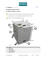
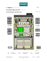
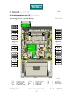
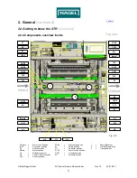
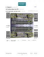
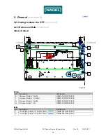
2.2.2 Components overview Inside
Fig. 2.8
Front-view
Outfeed
Infeed
J2/P2
J1/P1
PCB2
FC3
PCB3
J-Motor2
FC1
J-Motor1
J6/P6
Motor2
Motor1
S10
PCB1
TR1
Trafo1
Motor5
TR13
PCB4
C1
FC7
K1+K2
DB1
J9/P9
J4/P4
PCB8
PCB7
PCBx
= Printboard position
J-Motorx
=
Motor conn. Position
TRx
=
Terminal Rail
Jx/Px
= Connector position
FCx
=
Sensor
position
DBx
=
Rectifier
position
Sx
=
Switch
position
Motorx =
Motor
position
Cx
=
Capacitor
postion
Trafox
= Transformer position
Kx
=
Relais position
FC4


