

GT20 Control Wiring and Programming Manual
Part #C-00140
Rev. 10-7-16
7-32
Programming
Element
Default
Value
Description
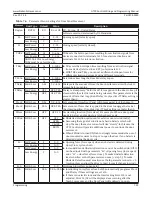
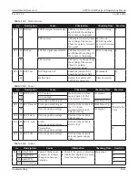
The following Table is only displayed when an optional Relay Board is installed
RC 0.1
RC 0.2
RC 0.3
RC 0.4
CLOSED
OPEN
ERROR
GONG
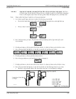
Only (1) PCB Terminal per Switch Activation is allowed. For example (2) activations (during
closing and opening) must be wired to (2) different PCB Terminals.
Note: The Configurator Menu will only display the following Elements/Values when the
Relay PCB Board is intalled.
Note: NABCO does not install more than (1) Relay PCB Board.
CLOSED
Relay switches when the Door Panel is fully closed.
OPENNG
Relay switches when the Door Panel is opening.
OPEN
Relay switches when the Door Panel is fully open.
CLOSING Relay switches when the Door Panel is closing.
ERROR
Relay switches if the GT20 Control detects an Error(s).
PSAUTO
Relay switches when the Program Selector is in Mode: AUTOMATIC
PSNIGHT Relay switches when the Program Selector is in Mode: NIGHT
PSEXIT
Relay switches when the Program Selector is in Mode: EXIT
PSOPEN
Relay switches when the Program Selector is in Mode: OPEN
PSMANU
Relay switches when the Program Selector is in Mode: MANUAL
GONG
Relay switches momentarily during the time the GT20 Control recieves a signal
from: Terminal 12 and Terminal 13 (Opening Command Inside).
LOCKED
Relay switches during the time the Door Panel is LOCKED with an electric lock.
Table 7-8
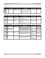
Double Door Menu: Settings for Closing Sequence and Interlock Function
Element
Default
Value
Description
DubleD
OFF
MastrA
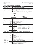
Doors Panels installed SidebySide.
SlaveA
InterL
OFF
Side A
Two individual door Panels that are connected by CAM Bus. One Door Panel
cannot open if the other door is open. Also known as AirLock or Mantrap.
Side B
Table 7-9
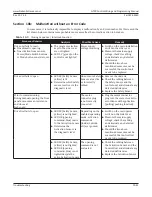
Diagnostic Menu: Diagnostic Tool
Element
lu
Description
K-I-O-R-S-P
-E
Displays all Input Commands (+) Active, (-) Inactive. Read Only, can not edit.
(K) Key
Night Mode Activation Devise
(I) OEI
Interior Activation Sensor
(O) OEO
Exterior Activation Sensor
(R) SER
Push Side Door Mounted Sensor
(S) SES
Swing Side Door Mounted Sensor
(P)
Swing Side Header Mounted Presence Sensor
(E) EMY-IN Emergency Open Input
-0.0A; 0°
Displays Motor Current and the Swing door opening angle (Example: 5.1A; 95°).
x.yA / z°
Displays actual current used by the Motor and the current Angle of the Door Panel.
X°C / y z
Displays the:
X
Current temperature measured on the PCB (Logic Print) on the first and second line.
X
Current minimum and maximum temperature since the last reset system.
OK will reset any/all stored (Min/Max. Values)
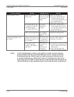
SimulateKey Key Command that opens the Door Panel by pressing OK
E-Lock
L Displays the status of the Lock.
L+
Locked
L-
Unlocked
FB Displays input El-FB. Press OK to actuate the
Electric Lock.
FB+ Locked
FB- Unlocked
PG Version Packaged Software
SW Version Version of Software


