


GT20 Control Wiring and Programming Manual
Part #C-00140
Rev. 10-7-16
4-8
Programming the GT20 Control
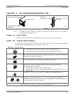
CHAPTER 4: PROGRAMMING THE GT20 CONTROL
Do not place finger or uninsulated tools inside the electrical GT20 Control. Touching wires or other parts
inside the enclosure may cause electrical shock, serious injury or death.
Shut Breaker OFF. Failure to do so may result in serious personal or fatal injury. When uncertain whether
power supply is disconnected, always verify using a voltmeter.
DN 1209
②
④
⑤
⑥
⑦
⑧
⑨
⑩
⑪
⑭ ⑮
⑬
⑯
⑱
⑰
②
②
③
①
⑫
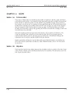
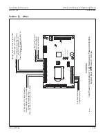
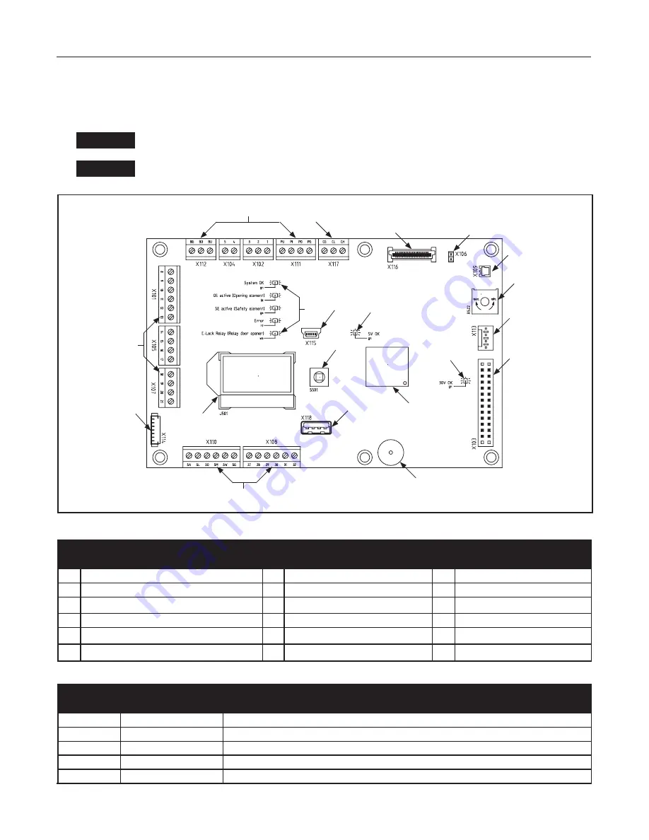
Table 4-1
Terminals (1-13)
#
Description
#
Description
#
Description
1
Power/Program Selector Switch
7
Reference Switch Connection
13 Joystick
2
Connection Terminals
8
Potentiometer (FSlam)
14
LEDs
3 LCD Display
9
Connection to Encoder
15 Serial Port
4
CAN Bus Port
10
Connection to Power Supply
16
Status LED = green
5 Processor
11
Buzzer
17
Status LED = green
6
Relay PCB Board (available March 2016)
12
USB Port
18
Jumper
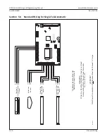
Table 4-2
LEDs (14)
LED
Description
Indicator
SOK
System OK
green flashing
OE active
Opening Element
blue = activ
SE active
Safety Element
yellow = activ
ERROR
ERROR
red
E-Lock Relay E-Lock Relay
white
DANGER
DANGER


