


Rev. 10-7-16
Part #C-00140
GT20 Control Wiring and Programming Manual
The Power/Program Selector
3-7
CHAPTER 3: THE POWER/PROGRAM SELECTOR
DN 1186
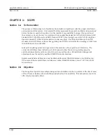
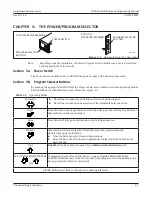
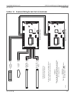
PROGRAM SELECTOR
BUTTONS
POWER SWITCH
GT20 OPERATOR ASSEMBLY
GT20 OHC
OPERATOR ASSEMBLY
Nigh
t
Exit
Auto
ma
c
Hold Open
Manua
l
PROGRAM SELECTOR
BUTTONS
Figure 3-1
Operate the Operator Assembly
Note: Depending upon the installation, the Power/Program Selector Switch may have to be installed
on the opposite side of the Header.
Section 3a: Power Switch
The Power Switch is utilized to turn ON/OFF the power supply to the Operator Assembly.
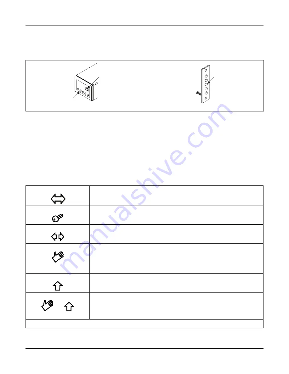
Section 3b: Program Selector Buttons
By pressing the appropriate LED Button, the Program Selector is utilized to activate Operating Modes.
Each LED Button is identified by an Icon. Please see Figure 3-1.
Table 3-1
Operating Modes
Automatic
X
Door Panel is opened by an Activation Device or a Knowing Act.
X
Door Panel is closed upon expiration of the adjustable hold-open time.
Night
Door Panel can only be opened by an Activation Device connected to a Key Terminal
(Example: an exterior card reader).
Open
Door Panel will fully open and remain in the Full Open position.
Manual
All activation devices are ignored, Door Panel must be opened manually.
An Internal Spring is utilized to:
X
Close the Door Panel for Standard Applications.
X
Open the Door Panel for Inverse Applications (unless the Door Panel has not
been locked).
Exit
One Way
: The Door Panel is opened by an
Interior Activation Device
only.
SET-UP PROCEDURE (TEACH)
plus
Completely close the Door Panel (Invers = open). Hold the Buttons MANUAL
and EXIT simultaneously at least 5 seconds. All pending errors will be deleted and a
set-up procedure (Teach) is carried out.
All LED Buttons will flash in the event of a pending fatal error.


