


Rev. 10-7-16
Part #C-00140
GT20 Control Wiring and Programming Manual
General Wiring
5-21
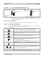
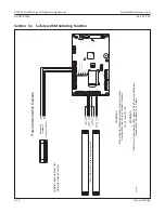
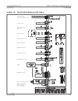
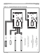
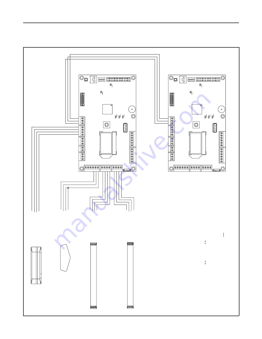
Section 5l: Standard Wiring for Sim Pair Full-Automatic
DN 1524
SA
SL
SO
SM
SW
X1
10
X108
27
28
29
30
31
18 19 20 21
X107
14 15 16 17
X105
10 11 12 13
89
X101
X1
12
54
31
2
X104
X102
X1
18
X103
X113
R552
X109
U501
S501
X114
X1
16
30V OK
OE active (Opening element)
System OK
SE active (Safety element)
gn
bl
ge
5V OK
max.
min.
32
gn
gn
PG
PO
PI
PU
CG
CH
CL
X1
17
SG
X1
11
BG
BU
BD
14
15
17
18
19
21
CO
M
N.C.
PWR+
PWR-
CO
M
N.C.
PWR+
PWR-
Swing-Side
Door Mounted
Sensor
Approach-Side Door Mounted
Sensor
Overhead
Presence Sensor
(if used)
CO
M
N.O.
PWR+
PWR-
PG
PO
16
20
PI
PU
11 12 13
CO
M
N.O.
PWR+
PWR-
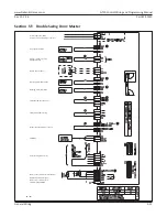
Activation Sensor
WA
RNING!
When A
ny Door Mounted Sensor Input is not Used,
A
Jumper Must Be In Place
At
Input T
erminal
s
15
16, and 19
20.
WA
RNING!
To
tal Power Consumption Of
Al
l Sensors
Must Not Exceed 1.2
Amps.
All Safety Sensors Must Use Normally Closed Contact
s
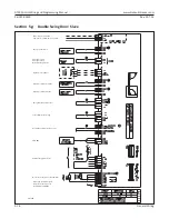
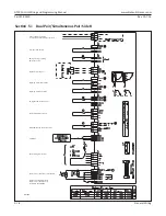
SLA
VE CONTROL
MASTER CONTROL
Any device connected to the Master Control
will only aff
ect the master
, not the slave.
CG-BLACK
CL-WHITE
CH-RED
CG-BLACK
CL-WHITE
CH-RED
SA
SL
SO
SM
SW
X1
10
X108
27
28
29
30
31
18 19 20 21
X107
14 15 16 17
X105
10 11 12 13
89
X101
X1
12
54
31
2
X104
X102
X1
18
X103
X113
R552
X109
U501
S501
X114
X1
16
30V OK
OE active (Opening element
)
System OK
SE active (Safety element)
gn
bl
ge
5V OK
max.
min.
32
gn
gn
PG
PO
PI
PU
CG
CH
CL
X1
17
SG
X1
11
BG
BU
BD


