


GT20 Control Wiring and Programming Manual
Part #C-00140
Rev. 10-7-16
5-10
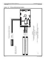
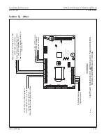
General Wiring
CHAPTER 5: GENERAL WIRING
Route the wiring away from moving parts or sharp edges likely to cause damage to
this wiring.
Any external switches has to be installed in a location from which operation of the
Door can be observed by the person operating the switch.
Appliance must be disconnected from the source of supply before attemping the
installation of accessories.
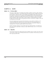
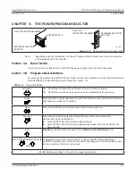
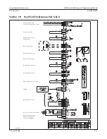
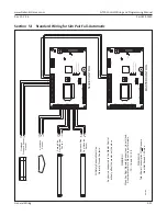
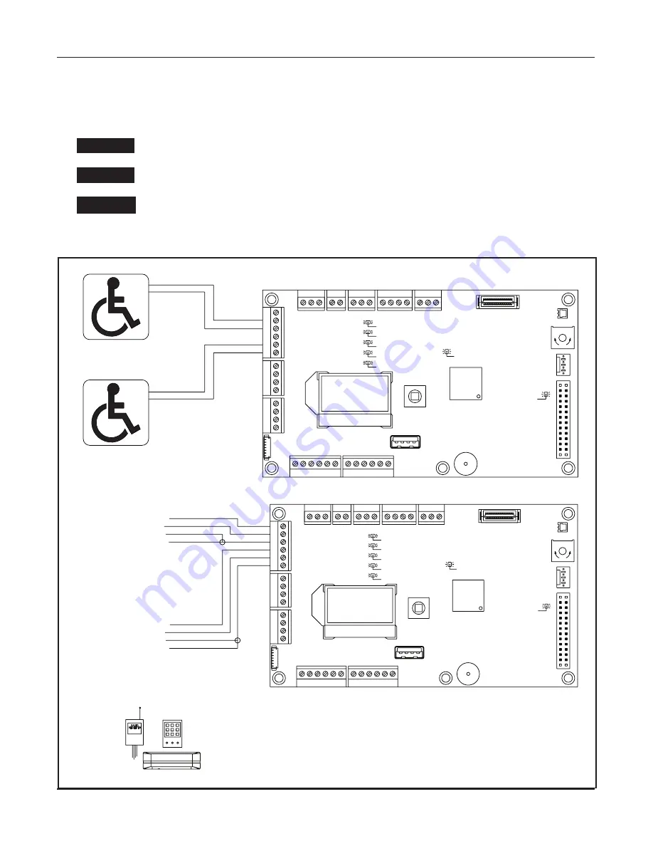
Section 5a: Activation Devices
DN 1261
Power Ac va on Devices: Sensors,
Card Readers, Radio Receiver, etc...
All Devices Must Be N.O. Dry Contact
NONPOWERED ACTIVATION DEVICES
POWERED ACTIVATION DEVICES
Exterior Push Plate
Interior Push Plate
RADIO
RECEIVER
!!!WARNING!!!
Total Power Consump on of ALL Sensors
and Powered Ac va on Devices
MUST NOT Exceed 1.2 Amps
Exterior
Ac va on
Device
Interior
Ac va on
Device
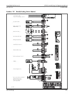
SA SL SO SM SW
X110
X108
27 28 29 30 31
18
19
20
21
X107
14
15
16
17
X105
10
11
12
13
8
9
X101
X112
X104
X102
X118
X103
X1
13
R55
2
X109
U501
S501
X1
14
X116
30V OK
OE active (Opening element)
System OK
SE active (Safety element)
green
blue
yellow
5V OK
max.m
in.
32
green
green
PG
PO
PI
PU
CG
CH
CL
X117
SG
X111
BG
BU
BD
ERROR
E-Lock Relay
red
white
8
9
10
11
12
13
COM
N.O.
PWR+
PWR-
COM
N.O.
PWR+
PWR-
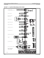
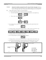
SA SL SO SM SW
X110
X108
27 28 29 30 31
18
19
20
21
X107
14
15
16
17
X105
10
11
12
13
8
9
X101
X112
2
X104
X102
X118
X103
X1
13
R55
2
X109
U501
S501
X1
14
X116
30V OK
OE active (Opening element)
System OK
SE active (Safety element)
green
blue
yellow
5V OK
max.
min.
32
green
green
PG
PO
PI
PU
CG
CH
CL
X117
SG
X111
BG
BU
BD
ERROR
E-Lock Relay
red
white
COM
N.O.
10
9
13
12
COM
N.O.
5 4
3
1
2
5 4 3
1
WARNING
WARNING
CAUTION