GT20 Control Wiring and Programming Manual
Part #C-00140
Rev. 10-7-16
9-40
Relay Print
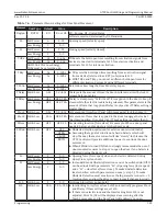
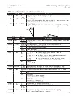
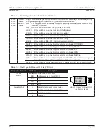
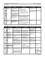
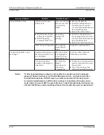
Table 9-1
The Configuration Menu for the Relay PCB Board
RC 0.1
RC 0.2
RC 0.3
RC 0.4
CLOSED
OPEN
ERROR
GONG
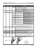
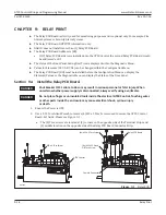
Only (1) PCB Terminal per Switch Activation is allowed. For example (2) activations (during
closing and opening) must be wired to (2) different PCB Terminals.
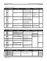
Note: The Configurator Menu will only display the following Elements/Values when the Relay
PCB Board is intalled.
Note: NABCO does not install more than (1) Relay PCB Board.
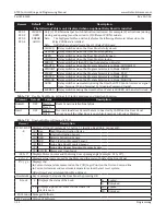
CLOSED
Relay switches when the Door Panel is fully closed.
OPENNG
Relay switches when the Door Panel is opening.
OPEN
Relay switches when the Door Panel is fully open.
CLOSING Relay switches when the Door Panel is closing.
ERROR
Relay switches if the GT20 Control detects an Error(s).
PSAUTO
Relay switches when the Program Selector is in Mode: AUTOMATIC
PSNIGHT Relay switches when the Program Selector is in Mode: NIGHT
PSEXIT
Relay switches when the Program Selector is in Mode: EXIT
PSOPEN
Relay switches when the Program Selector is in Mode: OPEN
PSMANU
Relay switches when the Program Selector is in Mode: MANUAL
GONG
Relay switches momentarily during the time the GT20 Control recieves a signal
from: Terminal 12 and Terminal 13 (Opening Command Inside).
LOCKED
Relay switches during the time the Door Panel is LOCKED with an electric lock.
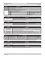
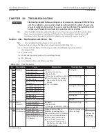
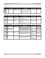
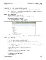
Table 9-2
The Diagnostic Menu for the Relay PCB Board
Diagnostic Element
Address
Description
Joystick
Display
R0+R1-
FP-RP-
Only (1) Relay PCB Board (R0)
has been installed
RO+R1-
FP-RP-
Displays what the Door Panel is doing
RO
Address for Relay Board (RC 0)
R1
N/A
FP
N/A
RP
N/A
Status Symbol
+
Identified and ready for operation
-
Neither identified nor registered
e
Defective or Error
x
Removed


