GT20 Control Wiring and Programming Manual
Part #C-00140
Rev. 10-7-16
7-30
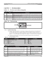
Programming
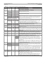
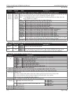
Element
Unit Type Default
Value
Description
LowEn Low Energy
OFF
OFF
Door Panel is Full Power in both directions
ON
X
Door Panel is Low Energy in both directions
X
Door Panel is activated by a Knowing Act
Width
30in... 48in
Weight
100lbs... 200lbs
Ao
Full & Low
90°
20°...190° Opening angle of the door (angle open)
Teach must be activated after this setting has been changed.
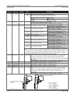
Rod
Full & Low STD-PH
STD-PH Outswing Arm and Arm Shoe
Push Function = Right Hand
Motor Cable Connector: X = Orange
SLI-PL
Inswing Arm and Track
Pull Function = Left Hand
Motor Cable Connector: Y = Green
SLI-PH Inswing Arm and Track
Push Function = Right Hand
Motor Cable Connector: X = Orange
WIN-PH Non-Applicable
Non-Applicable
DIR-PH Outswing Arm and Track
PushFunction = Right Hand
Motor Cable Connector: X = Orange
DIR-PL Outswing Arm and Track
Pull Function = Left Hand
Motor Cable Connector: Y = Green
OHC-PH Overhead Concealed
Push Function = Right Hand
Motor Cable Connector: X = Orange
OHC-PL Overhead Concealed
Pull Function = Left Hand
Motor Cable Connector: Y = Green
X
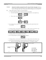
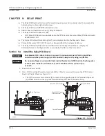
If panic breakout latch is installed and the motor is plugged in backwards or the
wrong arms are chosen during programming, there is a possibility the door can
burst open unexpectedly towards the installer once TEACH mode is initiated.
X
Teach must be activated after this setting has been changed.
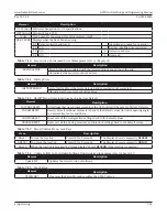
Inverse Full & Low
OFF
OFF...ON In the event of a power failure/error, the Door Panel is opened by
spring power from any position (unless it has been locked). The
position of the motor connector is reversed with regard to the standard
drive unit.
Teach must be activated after this setting has been changed.
AcSeq
Full & Low
0
0
0
0...
105
0
Delay Angle for Master opening sequence control.
TcSeq
Full & Low
1.5s
0.0...?
Delay Time for Master to begin to close the Door.
AoSeq
Full & Low
0
0
0
0...
105
0
Delay Angle for Slave opening sequence control.
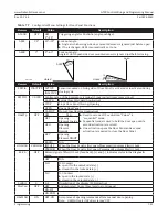
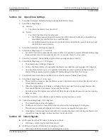
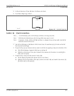
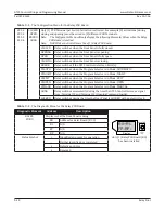
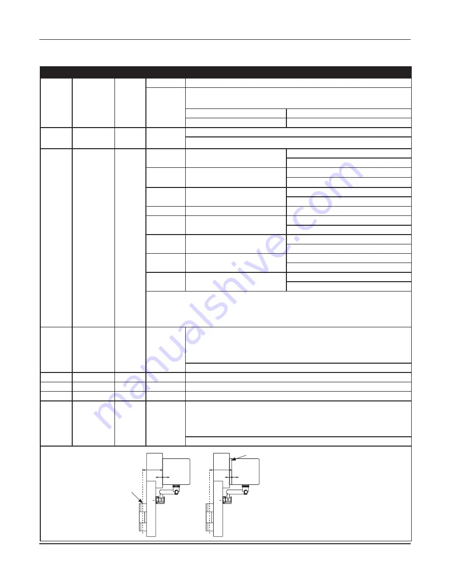
dAxis Full & Low
2.8in
-3.2...10in Distance between center line of the door hinges and the mounting
surface of the Operating Assembly. dAxis is an approximate value.
Depending on the installation situation, dAxis may have to be
estimated.
Teach must be activated after this setting has been changed.
DN 1181
Centerline of Door Pivot
or Hinge
dAxis
Moun ng Plate (op on)
+ —
dAxis
+ —
1 cm = 3/8 inch
2 cm = 3/4 inch
3 cm = 1-3/16 inch
4 cm = 1-1/2 inch
5 cm = 2 inch
6 cm = 2-3/8 inch


