background image


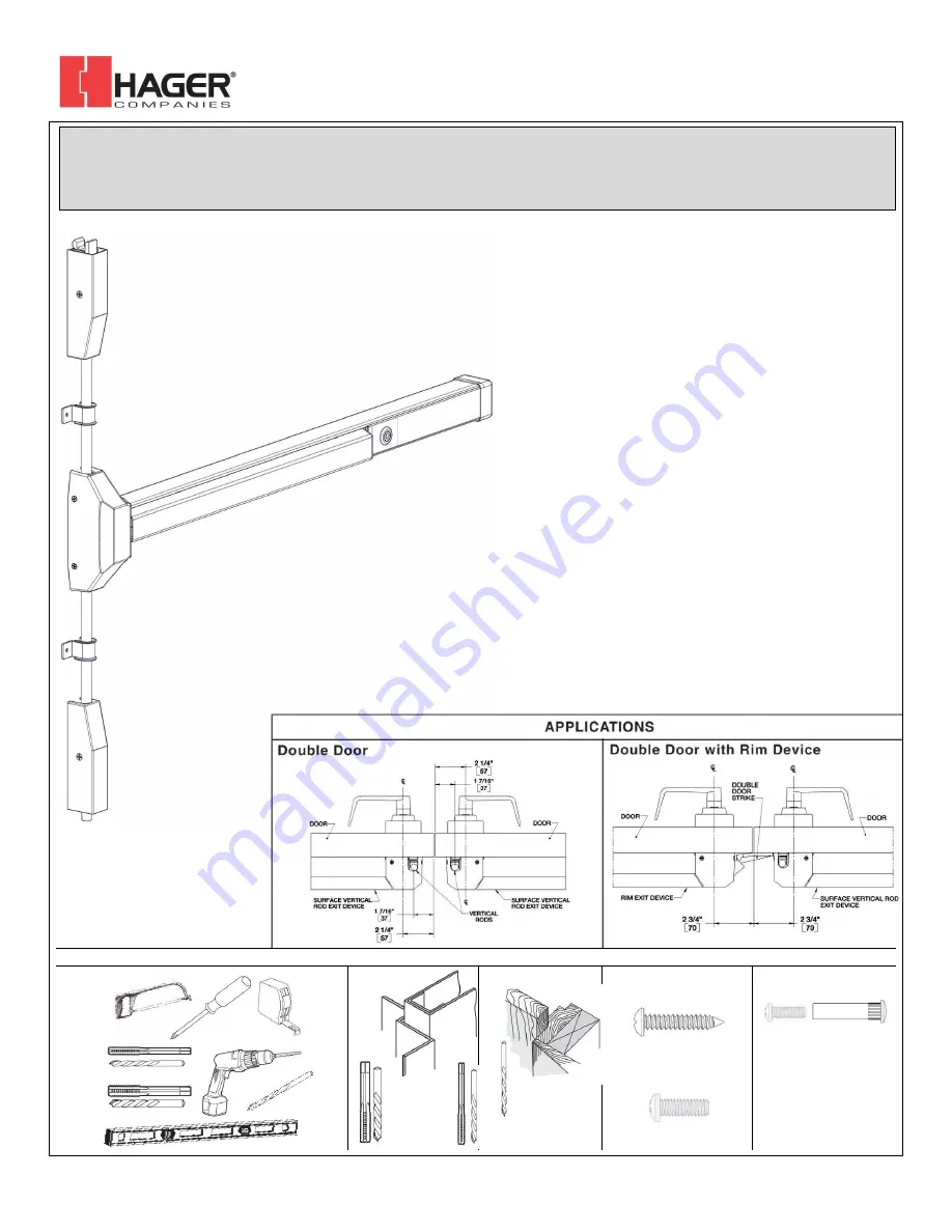
4700 Series Surface Vertical Rod Exit Device  


Installation Instructions 

Grade 1 


I-ED00793 

Rev 4, Rev Date: 05/31/2018 


 Page 1 of 


Hager Companies  139 Victor Street, St. Louis, MO 63104   (800) 325-9995   www.hagerco.com 


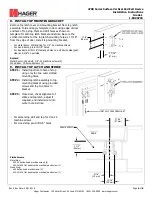
TOOLS REQUIRED 


Metal 


Wood 


Wood and Metal 

Screws 


For wood doors, drill 

1/8” hole


Machine Screws 


#7 drill, ¼”-20 tap 

#16 drill, #12-24 tap 

Sex Bolts 


Drill 5/16” thru from device 

side. Drill 3/8” from other side 

(pull side). 

Check building and fire codes 

to see if your application 

requires the use of sleeve 

nuts and bolts.


DEVICES COVERED IN THIS DOCUMENT: 
4700S Panic Surface Vertical Rod Device 


4700L Panic Less Bottom Rod (LBR) Device 

4700SF Fire Exit Surface Vertical Rod Device 

#16 Drill 

#12-24 Tap 

#7 Drill 

¼”-20 Tap 

1/8” Drill 

Summary of Contents for 4700S

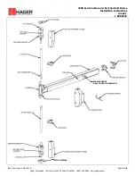
Page 1: ...or wood doors drill 1 8 hole Machine Screws 7 drill 20 tap 16 drill 12 24 tap Sex Bolts Drill 5 16 thru from device side Drill 3 8 from other side pull side Check building and fire codes to see if you...

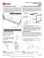
Page 2: ...od Exit Device Installation Instructions Grade 1 I ED00793 Rev 4 Rev Date 05 31 2018 Page 2 of 8 Hager Companies 139 Victor Street St Louis MO 63104 800 325 9995 www hagerco com DOGGING DEVICE ONLY ON...

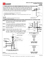
Page 3: ...d holes on pull side Trim requires an additional clearance hole for the trim actuating shaft If using Sex Bolts drill 5 16 clearance holes on exit device side of door push side 3 8 on pull side 3 INST...

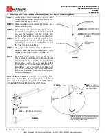
Page 4: ...ews 2 Wood door 12 wood screws 2 6 INSTALL BOTTOM STRIKE Skip this step if using a panic threshold or installing as LBR STEP 1 Bottom strike anchor location should already be marked If not extend bott...

Page 5: ...ine up see detail A STEP 5 Use the provided machine screw to attach rod to actuating plate Be sure actuating plate on the chassis is in the down position see detail A NOTE The bottom latch assembly ha...

Page 6: ...16 clearance holes on exit device side push side and 3 8 on pull side Screws Metal doors or Sex Bolt 1 4 20 machine screws 2 Wood door 12 wood screws 2 9 INSTALL TOP LATCH AND STRIKE STEP 1 Install to...

Page 7: ...e that was just drilled into the rod Use a hammer to tap the provided spring pin into the hole until it is fully seated Check that there is a secure connection between the rod and rod connector STEP 7...

Page 8: ...h will shorten the overall distance This will allow the top latch to completely rotate out of the way of the strike If the top latch will not stay in unlocked position after opening door Check that th...

Reviews: