


4700 Series Surface Vertical Rod Exit Device
Installation Instructions
Grade 1
I-ED00793
Rev 4, Rev Date: 05/31/2018
Page 7 of 8
Hager Companies 139 Victor Street, St. Louis, MO 63104 (800) 325-9995 www.hagerco.com
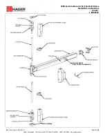
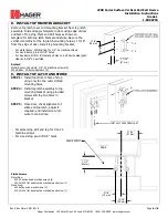
10.
INSTALL TOP ROD
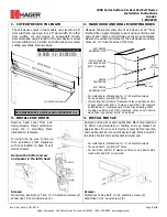
STEP 1:
Thr
ead top rod half-way onto top latch threaded connector.
STEP 2: Use the provided machine screw to attach rod connector onto
actuating plate, but do not attach top rod and rod connector yet.
Align the edge of rod connector next to top rod and mark a cutting
line on top rod. Be sure actuating plate on the chassis is in the down
position.
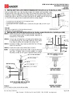
STEP 3: Remove top rod and cut top rod with hack saw or metal cutting saw
blade. Deburr edges.
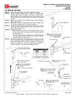
STEP 4: Slide newly cut rod into drilling guide until it stops. Drilling guide
sets the hole location so be sure rod is fully inserted.
STEP 5: Lay the rod with the drilling guide flat on a table. Use one of the
existing 1/8” guide holes on any side of the drilling guide and drill
an 1/8” hole through the rod.
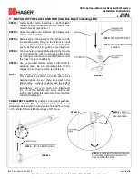
STEP 6: Install rod connector:
-
Slide the rod connector into the newly drilled end of the rod and
line up the hole in the rod connector with the hole that was just
drilled into the rod.
-
Use a hammer to tap the provided spring pin into the hole until
it is fully seated. Check that there is a secure connection
between the rod and rod connector.
STEP 7: Be sure the top latch is in the locked position. Thread top rod half-
way onto top latch threaded connector. Fasten bottom end of top
rod onto actuating plate on exit device chassis. This may require
raising or lowering the top rod by threading it clockwise or
counterclockwise on the top
latch threaded connector.
STEP 1: THREAD TOP ROD ONTO
TOP LATCH CONNECTOR
STEP 2: INSTALL ROD CONNECTOR
AND USE EDGE TO MARK WHERE
TO CUT TOP ROD
STEP 3: CUT TOP ROD WITH HACKSAW
ROD CONNECTOR
CUTTING EDGE
Rod (Cut to proper length)
Drilling Guide
STEP 4: FULLY INSERT ROD INTO
DRILLING GUIDE
STEP 5: DRILL 1/8” THRU HOLE USING
THE GUIDE HOLE AND DRILL ON A FLAT
SECURE SURFACE
Rod (Cut to
proper length)
Drilling Guide
1/8” Drill Bit
Drill Guide Hole
Completed Rod with
Spring Pin Connection
Rod
Spring Pin
Rod Connector
STEP 6: DRIVE SPRING PIN INTO
ROD / ROD CONNECTOR WITH A
HAMMER TO SECURE
STEP 7: INSTALL TOP ROD. THREAD
ROD ONTO TOP LATCH CONNECTOR.
FASTEN ROD CONNECTOR TO
ACTUATING PLATE.
TYPICAL TOP ROD LENGTH
DOOR
HEIGHT
ROD
LENGTH
6’ 8”
31 ¼”
7’
35 ¼”
8’
47 ¼”
THIS CHART REPRESENTS THE TYPICAL LENGTH
OF THE TOP ROD WITHOUT THE ROD CONNECTOR


