


4700 Series Surface Vertical Rod Exit Device
Installation Instructions
Grade 1
I-ED00793
Rev 4, Rev Date: 05/31/2018
Page 3 of 8
Hager Companies 139 Victor Street, St. Louis, MO 63104 (800) 325-9995 www.hagerco.com
1.
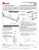
CUT EXIT DEVICE TO LENGTH
2.
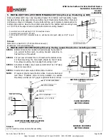
MARK DOOR AND DRILL MOUNTING HOLES
The exit device comes in two models, one sized for a 36”
door width and one sized for a 48” door width. For other
door widths, cut exit device to appropriate length.
Recommended overall length of the exit device is equal
to door width minus 4 inches. Cut with hack saw or metal
cutting saw blade. Deburr edges.
DOOR WIDTH RANGE FOR EXIT DEVICES
36” MODEL
30” – 36” DOOR WIDTH
48” MODEL
36” – 48” DOOR WIDTH
Measure horizontal center line of exit device at 40” from
finished floor. Apply template to door using centerline and
edge of door. Mark and drill holes as shown on template.
Be sure the vertical centerline for the exit device mounting
holes is 2 ¼” from the edge of the door.
-
For metal doors, drill and tap for ¼”-20 machine screws
-
For wood doors, pre-drill 1/8” holes
-
If mounting trim, drill 5/16” clearance holes on exit device side
of door (push side) and ½” holes on pull side. Trim requires
an additional ½” clearance hole for the trim actuating shaft.
-
If using Sex Bolts, drill 5/16” clearance holes on exit device
side of door (push side) & 3/8” on pull side
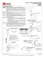
3.
INSTALL EXIT DEVICE
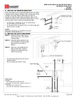
4.
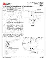
INSTALL END CAP
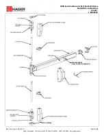
Remove head cover from exit
device chassis. Mount exit device
using the 2 mounting holes
indicated on template.
If using trim, be sure to line up
trim actuating shaft (tailpiece)
with cam located on back of exit
device chassis.
Remove the bottom screw
and spacer in the latch head
Screws:
Metal door, Sex Bolt, or Trim: ¼”-20 machine screws (2)
Wood door: #12 wood screws (2)
Remove end cap from end cap bracket. Mark hole locations
by either using template or holding end cap bracket up
against door. Be sure exit device is level before inserting
end cap bracket lip into end of device body. Mark and drill /
tap holes. Install end cap bracket and end cap.
-
For metal doors, drill and tap for ¼”-20 machine screws
-
For wood doors, pre-drill 1/8” holes
-
For Sex Bolts, drill 5/16” clearance holes on exit device side
(push side) and 3/8” on pull side.
Screws:
Metal door or Sex Bolt: ¼”-20 machine screws (2)
Wood door: #12 wood screws (2)
RECOMMENDED EXIT DEVICE LENGTH=DOOR WIDTH – 4”
EXIT DEVICE
MOUNTING HOLE
DEVICE
CENTERLINE
TRIM ACTUATOR
CLEARANCE HOLE
Ø1/2” (if required)
EXIT DEVICE
MOUNTING HOLE
2 7/8”
(73 mm)
2 ¼”
(57 mm)


