


SUPREMATouch
160
Installation
MSA
US
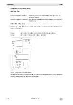
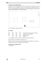
Fig. 87
Slots and Positions on the rack
Slots in the Rack
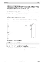
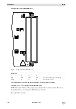
Connection sites on the rear of the rack:
Fig. 88
Rear of the Rack
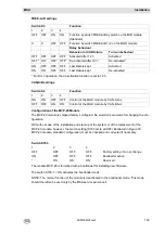
System Requirements
The following requirements must be fulfilled in order to build a functional system:
Exactly one MCP module, one MDC module and one MDO module are required for a system (up
to 8 racks) (non-redundant design). The MDC module must be properly connected by ribbon cable
to the MDO module mounted in the front panel.
Exactly one MDA module is required for a rack (non-redundant design) if MAI modules are also
present in the rack.
Slots 1-3:
slots for MCP and/or MDC modules only
Slots 4-5:
slots for MDA modules only
Slots 6-13:
slots for INPUT/OUTPUT modules
Slots 14-15:
slots for INPUT/OUTPUT (but no MAI) modules only
INPUT:
MAI modules (with MPI/MCI modules)
MBC modules
OUTPUT:
MGO module
MAO module
MBC module
MST:
connection site for the MST module only
(Positions 1-10):
connection site for:
- MAT module
(8 x 5 terminals)
- MUT module
(40-way ribbon cable)
- MRO 8 module (Position 9!)
MxT
MST
MxT MxT MxT MxT MxT MxT MxT MxT MxT
Pos.
9
Slot
14
Pos.
10
Slot
15
Pos.
8
Slot
13
Pos.
7
Slot
12
Pos.
6
Slot
11
Pos.
5
Slot
10
Pos.
4
Slot
9
Pos.
3
Slot
8
Pos.
2
Slot
7
Pos.
1
Slot
6
Slot
1
Slot
2
Slot
3
Slot
4
Slot
5
MAI
MAO
MGO
MBC
MAI
MAO
MGO
MBC
MAI
MAO
MGO
MBC
MAI
MAO
MGO
MBC
MAI
MAO
MGO
MBC
MAI
MAO
MGO
MBC
MAI
MAO
MGO
MBC
MAO
MGO
MBC
MAO
MGO
MBC
MAI
MAO
MGO
MBC
MDC
MCP
MDC
MCP
MDC
MCP MDA MDA
Rear:
Front:
EXT
INT
BAT
+
-
X2
1
+
-
+
-
X2
2
X2
3
PO
S
1
0
PO
S
9
POS
8
POS
7
PO
S
6
PO
S
5
POS
4
PO
S
3
PO
S
2
PO
S
1
1
2
3
4
5
6
S
YST
E
M
P
O
WER
M
S
P
1
0
N
L
P
E
G
N
D
G
N
D
+
2
4V
+
24V
RL2
RL1
ON
7
89
10
11
1
2
11
0
Summary of Contents for SUPREMA Touch
Page 2: ...Manual SUPREMATouch Fire and Gas Warning Unit Order No 10126972 00...
Page 7: ...SUPREMATouch 6 Contents MSA US...
Page 8: ...User Instruction Manual SUPREMATouch Fire and Gas Warning Unit...
Page 104: ...Service and Maintenance Guide SUPREMATouch Fire and Gas Warning Unit...
Page 112: ...Installation and Start Up Manual SUPREMATouch Fire and Gas Warning Unit...
Page 151: ...SUPREMATouch 150 Installation MSA US Fig 79 MCP Module standard configuration...
Page 303: ...SUPREMA 302 Dimensions MSA GB 16 Dimensions 16 1 Rack...
Page 306: ...MSA AUER MSA Dimensions SUPREMA 305 GB MRO20 8 TS Module 1 3 2 69 90...
Page 307: ...SUPREMA 306 Dimensions MSA GB MRO20 16 TS Module 2 5 2 64 73 relay dependent 90...
Page 308: ...MSA AUER MSA Dimensions SUPREMA 307 GB MRC TS Module MGT 40 TS Module...
Page 309: ...SUPREMA 308 Dimensions MSA GB MHD TS Module MAT TS Module...