


MSA AUER
MSA
Installation
SUPREMATouch
133
US
-
Check the suitability of the installation site and the cabling requirements.
-
Check the current and voltage supply and make sure it is suitable.
-
Depending on the type of system shipped, install the switch cabinet, or the 19” mounting rack.
-
Check the configuration of the modules and reconfigure if necessary.
-
Install the modules in the 19” mounting rack (unless already installed at the factory).
-
In the case of expanded systems with more than one 19” mounting rack, connect the CAN bus
or check the connection if it has already been made.
-
Install the sensors and connect the wiring to the SUPREMA.
NOTE: Follow the installation instructions for hazardous areas!
-
Connect the relay and current outputs to the external devices to be actuated.
-
Connect the current and voltage supply.
After installation is complete, perform the start-up procedure as instructed in Chapter 11.
Unpacking
Perform the following steps on receipt of the shipment:
Installation Site
The SUPREMA control unit may be installed only outside of areas subject to the danger of explo-
sion. The specified temperature and humidity conditions must also be satisfied, and contact with
corrosive substances must be avoided.
NOTE: The SUPREMA installation site must be outside of hazardous area Zones 0,1 and 2 and
be free of combustible, explosive or corrosive gases.
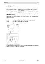
Cabling
The terminal posts on the
Analog Terminal Units
(MAT module and MAT TS module) are de-
signed for the connection of conductors with a cross section in the range of 0.2 ... 1.5 mm
2
.
The terminal posts on the
Relay Output Units
(MRO 8, MRO 8 TS, and MRO 16 TS modules)
are designed for the connection of conductors with a cross section in the range of 0.2 ... 2.5 mm
2
.
The terminal posts on the
External Connection Module MGT 40 TS
are designed for the con-
nection of conductors with a cross section in the range of 0.2 ... 2.5 mm
2
.
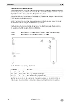
On the
Interconnection Board
(MIB module), the terminal posts for the connection of the supply
voltages are designed for conductor cross sections of 0.2 ... 4.0 mm
2
, and the terminals for the
system failure relays are designed for conductor cross sections of 0.14 ... 1.5 mm
2
.
On the
System Terminals Module
(MST module), the terminals for Alarm Reset, Horn Reset, Re-
lay Inhibit, and Key Switch are designed for conductor cross sections in the range of
0.2 ... 2.5 mm
2
. The
System Terminals Module
(MST module) also has 2 SUB-D plug connector
strips (9-way) for the connection of the CAN bus and 3 SUB-D socket terminal strips for RS 232
connections.
Carefully unpack the device or its components, observing all of the instructions printed on or ac-
companying the packaging.
Also inspect the contents of the delivery to determine if any transport damage has occurred and
verify that everything listed in the shipping papers has in fact been received.
Summary of Contents for SUPREMA Touch
Page 2: ...Manual SUPREMATouch Fire and Gas Warning Unit Order No 10126972 00...
Page 7: ...SUPREMATouch 6 Contents MSA US...
Page 8: ...User Instruction Manual SUPREMATouch Fire and Gas Warning Unit...
Page 104: ...Service and Maintenance Guide SUPREMATouch Fire and Gas Warning Unit...
Page 112: ...Installation and Start Up Manual SUPREMATouch Fire and Gas Warning Unit...
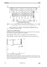
Page 151: ...SUPREMATouch 150 Installation MSA US Fig 79 MCP Module standard configuration...
Page 303: ...SUPREMA 302 Dimensions MSA GB 16 Dimensions 16 1 Rack...
Page 306: ...MSA AUER MSA Dimensions SUPREMA 305 GB MRO20 8 TS Module 1 3 2 69 90...
Page 307: ...SUPREMA 306 Dimensions MSA GB MRO20 16 TS Module 2 5 2 64 73 relay dependent 90...
Page 308: ...MSA AUER MSA Dimensions SUPREMA 307 GB MRC TS Module MGT 40 TS Module...
Page 309: ...SUPREMA 308 Dimensions MSA GB MHD TS Module MAT TS Module...