


SUPREMATouch
142
Installation
MSA
US
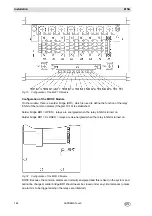
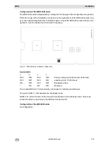
Configuration of MCI 20
No configuration
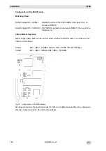
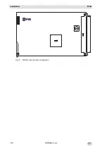
Configuration of MCI 20 BFE
No configuration
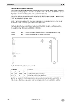
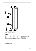
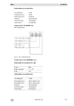
Configuration of the MAT Module
Two solder bridges are provided for each input on the bottom of the circuit board for 3 or 5 wire
operation of the sensors:
NOTE: The solder bridges for 3 wire operation must be closed only when passive sensors
(MPI module) are connected. For 5 wire operation with active sensors (MCI module), the solder
bridges must be open!
WARNING
Passive sensors should never be connected to an MCI module, as this may cause the destruc-
tion of the sensors and/or the MAI/MCI modules.
Solder bridge OPEN
= 5 wire operation
Solder bridge CLOSED
= 3 wire operation
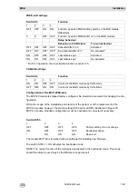
Assignment:
BR1, BR2
input 1
BR3, BR4
input 2
BR5, BR6
input 3
BR7, BR8
input 4
BR9, BR10
input 5
BR11, BR12
input 6
BR13, BR14
input 7
BR15, BR16
input 8
Summary of Contents for SUPREMA Touch
Page 2: ...Manual SUPREMATouch Fire and Gas Warning Unit Order No 10126972 00...
Page 7: ...SUPREMATouch 6 Contents MSA US...
Page 8: ...User Instruction Manual SUPREMATouch Fire and Gas Warning Unit...
Page 104: ...Service and Maintenance Guide SUPREMATouch Fire and Gas Warning Unit...
Page 112: ...Installation and Start Up Manual SUPREMATouch Fire and Gas Warning Unit...
Page 151: ...SUPREMATouch 150 Installation MSA US Fig 79 MCP Module standard configuration...
Page 303: ...SUPREMA 302 Dimensions MSA GB 16 Dimensions 16 1 Rack...
Page 306: ...MSA AUER MSA Dimensions SUPREMA 305 GB MRO20 8 TS Module 1 3 2 69 90...
Page 307: ...SUPREMA 306 Dimensions MSA GB MRO20 16 TS Module 2 5 2 64 73 relay dependent 90...
Page 308: ...MSA AUER MSA Dimensions SUPREMA 307 GB MRC TS Module MGT 40 TS Module...
Page 309: ...SUPREMA 308 Dimensions MSA GB MHD TS Module MAT TS Module...