MOTOROLA
Chapter 27. Queued Analog-to-Digital Converter (QADC)
27-69
Signal Connection Considerations
• Analog ground must be low impedance to all analog ground points in the circuit.
• Bypass capacitors should be as close to the power pins as possible.
• The analog ground should be isolated from the digital ground. This can be done by
cutting a separate ground plane for the analog ground.
• Non-minimum traces should be utilized for connecting bypass capacitors and filters
to their corresponding ground/power points.
• Minimum distance for trace runs when possible.
27.9.5 Accommodating Positive/Negative Stress Conditions
Positive or negative stress refers to conditions which exceed nominally defined operating
limits. Examples include applying a voltage exceeding the normal limit on an input (for
example, voltages outside of the suggested supply/reference ranges) or causing currents
into or out of the pin which exceed normal limits. QADC specific considerations are
voltages greater than V
DDA
or less than V
SSA
applied to an analog input which cause
excessive currents into or out of the input. Refer to MCF5282 Electrical Characteristics for
more information on exact magnitudes.
Either stress conditions can potentially disrupt conversion results on neighboring inputs.
Parasitic devices, associated with CMOS processes, can cause an immediate disruptive
influence on neighboring pins. Common examples of parasitic devices are diodes to
substrate and bipolar devices with the base terminal tied to substrate (V
SS
/V
SSA
ground).
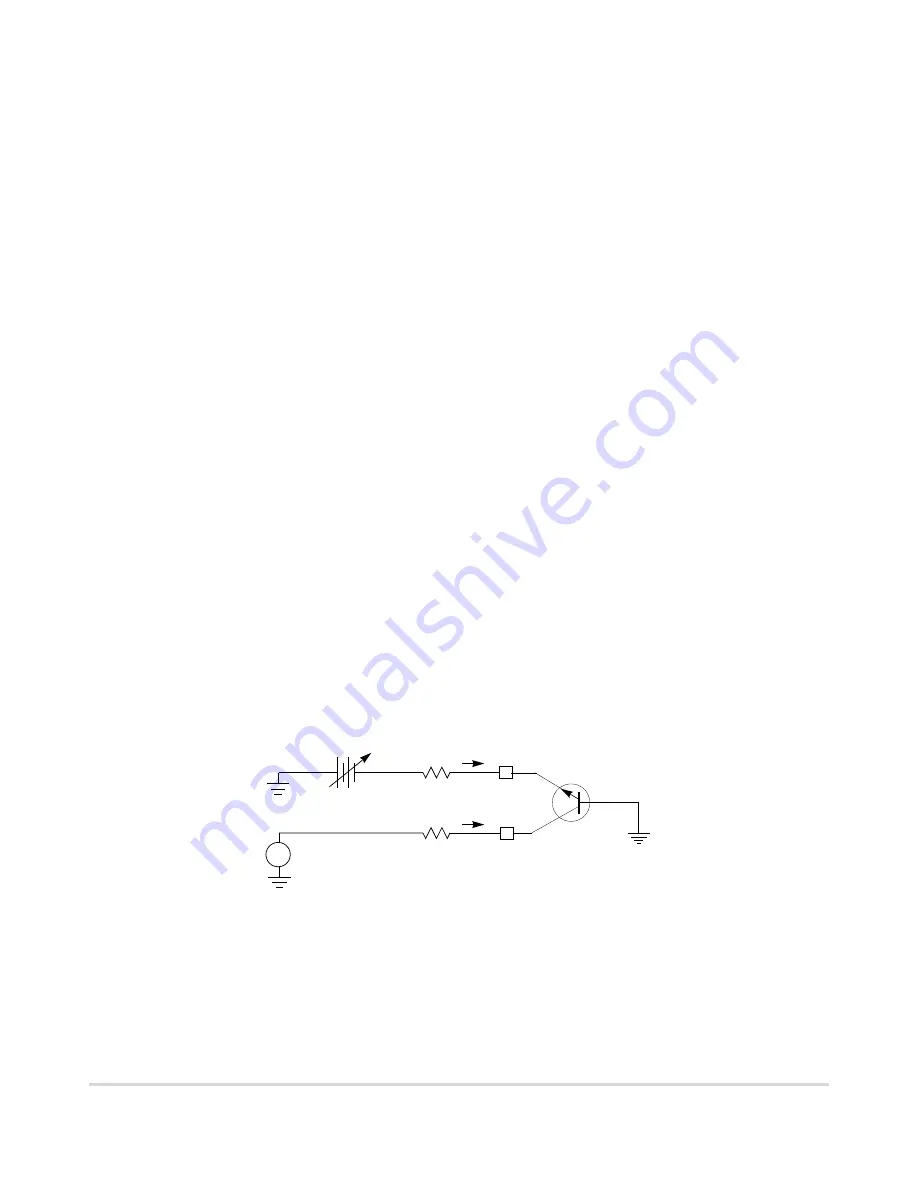
Under stress conditions, current injected on an adjacent signal can cause errors on the
selected channel by developing a voltage drop across the selected channel’s impedances.
Figure 27-50 shows an active parasitic bipolar NPN transistor when an input signal is
subjected to negative stress conditions. Figure 27-51 shows positive stress conditions can
activate a similar PNP transistor.
Figure 27-50. Input Signal Subjected to Negative Stress
R
STRESS
R
SELECTED
Adjacent
10 k
Ω
Signal Under
Parasitic
I
injn
I
IN
+
Stress
V
STRESS
Device
Signal
V
IN
AN
n
AN
n+1
Summary of Contents for ColdFire MCF5281
Page 124: ...3 20 MCF5282 User s Manual MOTOROLA EMAC Instruction Set Summary ...
Page 141: ...MOTOROLA Chapter 5 Static RAM SRAM 5 5 SRAM Programming Model ...
Page 142: ...5 6 MCF5282 User s Manual MOTOROLA SRAM Programming Model ...
Page 168: ...6 26 MCF5282 User s Manual MOTOROLA Interrupts ...
Page 186: ...7 18 MCF5282 User s Manual MOTOROLA Functional Description ...
Page 228: ...9 22 MCF5282 User s Manual MOTOROLA Functional Description ...
Page 246: ...10 18 MCF5282 User s Manual MOTOROLA Low Power Wakeup Operation ...
Page 254: ...11 8 MCF5282 User s Manual MOTOROLA Memory Map and Registers ...
Page 264: ...12 10 MCF5282 User s Manual MOTOROLA Chip Select Registers ...
Page 280: ...13 16 MCF5282 User s Manual MOTOROLA Misaligned Operands ...
Page 314: ...14 34 MCF5282 User s Manual MOTOROLA MCF5282 External Signals ...
Page 339: ...MOTOROLA Chapter 15 Synchronous DRAM Controller Module 15 25 SDRAM Example ...
Page 340: ...15 26 MCF5282 User s Manual MOTOROLA SDRAM Example ...
Page 356: ...16 16 MCF5282 User s Manual MOTOROLA DMA Controller Module Functional Description ...
Page 408: ...17 52 MCF5282 User s Manual MOTOROLA Buffer Descriptors ...
Page 446: ...20 24 MCF5282 User s Manual MOTOROLA Interrupts ...
Page 474: ...22 18 MCF5282 User s Manual MOTOROLA Programming Model ...
Page 510: ...23 36 MCF5282 User s Manual MOTOROLA Operation ...
Page 526: ...24 16 MCF5282 User s Manual MOTOROLA I2C Programming Examples ...
Page 672: ...28 12 MCF5282 User s Manual MOTOROLA Functional Description ...
Page 718: ...29 46 MCF5282 User s Manual MOTOROLA Motorola Recommended BDM Pinout ...
Page 750: ...32 8 MCF5282 User s Manual MOTOROLA Ordering Information ...


