


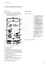


Incoming circuit-breaker RA-DI
01/08 AWB2190-1430GB
42
Device operation
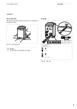
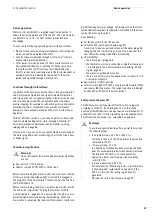
Switch on
Before commissioning, all cables of the Rapid Link busbar, the
external power supply and the der AS-Interface
®
must be
connected and the cable ends safely insulated. The enclosure must
be firmly secured with the screws.
The rotary handle is lockable in position 0 with up to three
padlocks.
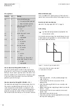
After tripping through overload or short-circuit, the switch jumps
from I to Trip.
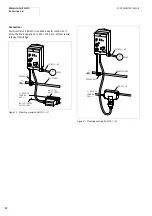
Figure 40: Connection to AS-Interface
®
and busbar (optionally
through ribbon cable RA-C1 or round cable RA-C2)
Figure 41: For additional protection of AS-Interface
®
from loosened
cables, fit the cover plate ( on ).
h
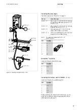
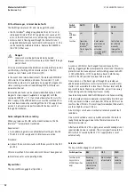
For connecting conductors
f
4 mm
2
to terminals 1.13/
1.14, suitable pin-end connectors are supplied.
ZB2-155-KB1
ZB2-100-AZ1
RA-C1-VM-7
RA-C2-S1-4
RA-C1-7
x
2.5 PVC
(RA-C1-7
x
4 HF)
7
x
2.5 mm
2
(7
x
4 mm
2
)
V-M25
7
x
2.5 mm
2
(7
x
4 mm
2
)
400 V
h
24 V
H
7
x
2.5 mm
2
(7
x
4 mm
2
)
6
2
1
5
4
3
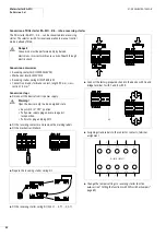
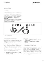
Figure 42: Rotary handle in position 0
Figure 43: Rotary handle in Trip position
j
Danger!
When the switch is in Trip position, it must be switched on
again only when the cause of tripping has been rectified!
Restarting is possible only via switch position 0.
Figure 44: Rotary handle in position 1
+
l
o
+
l
o
+
l
o
Summary of Contents for Rapid Link
Page 10: ...01 08 AWB2190 1430GB 6 ...
Page 40: ...01 08 AWB2190 1430GB 36 ...
Page 48: ...01 08 AWB2190 1430GB 44 ...
Page 70: ...01 08 AWB2190 1430GB 66 ...
Page 146: ...01 08 AWB2190 1430GB 142 ...
Page 162: ...01 08 AWB2190 1430GB 158 ...