


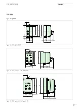
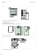

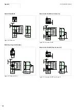


Appendix
01/08 AWB2190-1430GB
144
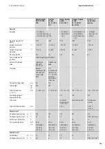
1) RA-MO2.x and RA-MO 24 V… only
2) plus power for actuator (03) for RA-MO…A…
3) plus power supply for connected sensors
Power loss
W
–
–
–
44
65
92
Motor circuit
Assigned motor rating
kW
–
–
0,09 to 3,0
0.37 to
0.75
0.75 to
?1.1?
1.1 to
2.2
Setting range, motor protection
A
–
–
0.3 to 6.6
(0.5 to 1.2)
x
I
e
electronic
Tripping class
A
–
–
10
–
Output voltage
U
L
V
h
–
–
U
e
0 to
U
e
Frequency range, Motor output
Hz
–
–
50 to 60
0.5 to 360
Control circuit
24 V
H
Rated voltage
U
e
V
H
30
–
24
24 (internal)
Tolerance
%
–
–
–15 to 20
–
Typical current consumption
at 24 V
H
mA
–
–
200
1) 2)
–
AS-Interface
®
Max. total power consumption
from AS-Interface
®
(30 V
H
power supply unit)
mA
200
90
50 – 200
3)
25 – 220
max. current supply in AS-
Interface
®
mA
2800
–
–
–
AS-Interface
®
specification
2.1
2.1
2.1
2.1
Slave addresses
Number
62
31
62
31
IO Code
or I/O configuration
–
7 (hex)
7 (hex)
7 (hex)
ID-code
–
F (hex)
A (hex)
E (hex)
ID1-Code
–
0 (hex)
Address:
xxA = o
xxB = F
0 (hex)
ID2-Code
–
E (hex)
D (hex)
0 (hex)
Inputs
Data input 0
DI0
–
Switch position (I1)
Automatic
Automatic
Data input 1
DI1
–
–
Group fault
Group fault
Data input 2
DI2
–
–
external input
RA-MO-4 (I3)
–
Data input 3
DI3
–
–
external input
RA-MO-4 (I4)
–
Outputs
Datenausgang 0
DO0
–
LED O1
Main contactor
Enable FWD rotation (right)
Datenausgang 1
DO1
–
–
Reversing contactor
Enable REV rotation (left)
Datenausgang 2
DO2
–
–
LED O3 or ext. output
RA-MO-4A(03)
Setpoints
Datenausgang 3
DO3
–
–
–
Setpoints
Mains connection cable
Terminal capacity
mm
2
–
–
1.5
1.5
RA-IN
RA-DI
RA-MO
RA-SP
..0.75..
..1K1..
..2K2..
Summary of Contents for Rapid Link
Page 10: ...01 08 AWB2190 1430GB 6 ...
Page 40: ...01 08 AWB2190 1430GB 36 ...
Page 48: ...01 08 AWB2190 1430GB 44 ...
Page 70: ...01 08 AWB2190 1430GB 66 ...
Page 146: ...01 08 AWB2190 1430GB 142 ...
Page 162: ...01 08 AWB2190 1430GB 158 ...