


Speed controller RA-SP
01/08 AWB2190-1430GB
130
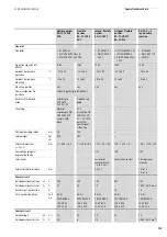
F-32 Frequency value signal FA2
The digital output configured as FA2 becomes active when the
frequency falls below the frequency set under PNU C42. FA2 is
deactivated as soon as the actual frequency falls below the value
set in PNU C42. If PNU F01 or PNU A20 is used for the reference
input, the frequency set with PNU C42 can be smaller than the
value in PNU C43. (
a
fig. 124)
To ensure system hysteresis, signal FA2 is activated each time the
actual frequency is 0.5 Hz below the frequency set with PNU C42
and deactivated 1.5 Hz past the frequency set with PNU C43.
X
If you configure a programmable digital output as FA2, you
must also, under PNU C42, enter the frequency from which the
FA2 signal is active during acceleration.
X
With PNU C43, set the respective frequency which is to remain
active until the FA2 signal is deactivated during deceleration.
Figure 124: Function chart for FA2 (frequency exceeded)
f
o
: Output frequency
h
The transition of an FA1 or FA2 signal from the inactive to
the active state takes place with a delay of about 60 ms.
FA2
PNU C42
PNU C43
f
O
0.5 Hz
1.5 Hz
60 ms
PNU
Designation
Adjustable in
RUN mode
Value
Function
FS
C42
Frequency from
which FA2
becomes active
during
acceleration
–
0 to 360 Hz
The digital output (2 or 11)
configured as FA12 becomes
active when the frequency
entered here is exceeded
during acceleration.
0,0
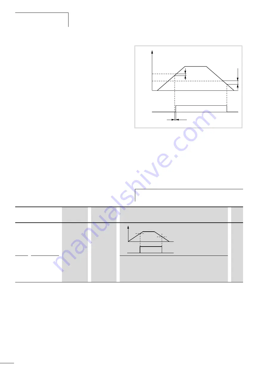
C43
Frequency at
which FA2
becomes inactive
during
deceleration
Digital output 11, configured as FA2, remains active during deceleration
as long as the actual frequency remains higher than the frequency
entered here (a also the illustration for PNU C42).
PNU C42
PNU C43
FA2
f
Summary of Contents for Rapid Link
Page 10: ...01 08 AWB2190 1430GB 6 ...
Page 40: ...01 08 AWB2190 1430GB 36 ...
Page 48: ...01 08 AWB2190 1430GB 44 ...
Page 70: ...01 08 AWB2190 1430GB 66 ...
Page 146: ...01 08 AWB2190 1430GB 142 ...
Page 162: ...01 08 AWB2190 1430GB 158 ...