


01/08 AWB2190-1430GB
Engineering
11
Data Transfer
Data is transmitted modulated through the power supply, the
station’s transmitter injecting the data signals into the line in the
form of current changes. These current changes induce a voltage
in the data coupling coils, which is detected by all stations’
receivers along the AS-Interface
®
line.
The cycle time is determined by the number of stations along the
busbar run, regardless whether the stations can have 31 or 62
addresses (A/B slaves). For 31 stations the cycle time is about 5 ms
and for 62 stations about 10 ms. The cycle time is calculated as
follows: 150 s x (number of st 1)
Background information for PLC technicians about the
function principle of parameter transmission in RA-MO,
RA-SP and RA-IN
Parameters are transmitted according to the possibilities provided
by the A
2
S-i microcontroller. Parameter bits P1 to P4 (bank A) sent
by the controller are provided to the RA-MO electronics
m
c (bank
B) unchanged. The data returned to the master (bank C) is
generated through an AND gate.
For slaves with A-address, parameter bit
on bank A is
automatically set to 1, and for slaves with B-address to 0 (for A- and
B-addresses, see section “Addressing slaves (with hand-held
addressing unit PG2-105-AD2)” on page 17.
When the PLC sends parameter bits P1 to P3 = 000 (A), only
parameter value 000 (C) is returned, regardless of the RA-MO
electronic’s status.
Reading out diagnostic status:
If the PLC sends the value 111 (A), the motor starter interprets this
as a request to return the diagnostic status. To allow correct
transfer of the diagnostic status (
table 2 on page 60), the PLC
must send only parameter value 111 until it receives the receive
data.
Parameter handling in RA-IN:
In the interface control unit RA-IN parameters are handled with
mailbox commands. With the command SET PP (set parameter
value) the PLC can permanently save a parameter value for each
slave in the EEPROM of the RA-IN. When it is switched on, the RA-
IN automatically sends these values to all slaves provided the
communication in the AS-i run is working). The parameter values
remain available even if the PLC fails.
With the command WRITE P (write parameter value) the PLC can
transfer a value other than the set parameter value to each AS-i
slave. This does not affect the parameter data written to the RA-
IN’s EEPROM with SET PP.
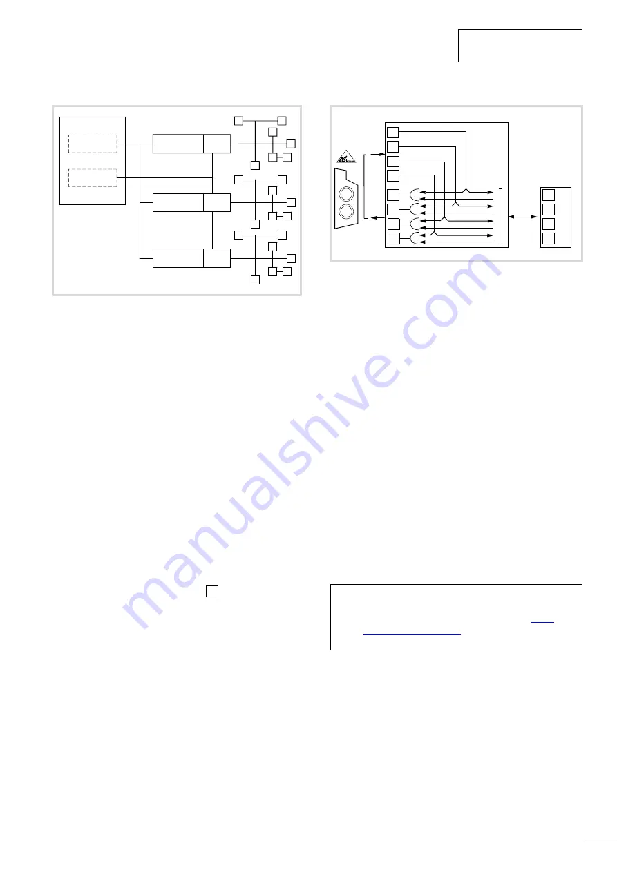
Figure 3:
AS interface
®
network in star design
PROFIBUS-DP
RA-IN
PEX
RA-IN
PEX
RA-IN
PEX
30 V
H
P4
Figure 4:
Function principle of parameter transmission
h
http://
www.moeller.net/support
: Search term: AWB2700-
1409G)
&
P3
&
P4
&
P1
&
P2
P3
P4
P1
P2
P3
P4
P1
P2
m
C
B
A
C
Summary of Contents for Rapid Link
Page 10: ...01 08 AWB2190 1430GB 6 ...
Page 40: ...01 08 AWB2190 1430GB 36 ...
Page 48: ...01 08 AWB2190 1430GB 44 ...
Page 70: ...01 08 AWB2190 1430GB 66 ...
Page 146: ...01 08 AWB2190 1430GB 142 ...
Page 162: ...01 08 AWB2190 1430GB 158 ...