


01/08 AWB2190-1430GB
Description of functions
107
Description of functions
Quick stop and interlocked manual mode with RA-SP-HE…
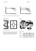
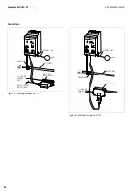
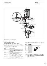
Speed control unit RA-SP2-HE… has two M12 sockets to which up
to four light barriers, sensors or limit switches can be connected.
The input signals at pin 4 of the M12 socket are transmitted to the
PLC as well as being internally processed. The input signals at
pin 2 are only processed internally and are not transmitted to the
PLC. With the DIP switch you can configure these inputs as Quick
Stop, Quick Stop with Creep Speed, Interlocked Manual Mode, or
Interlocked Manual Mode with Creep Speed.
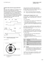
The Quick Stop function allows precision stopping of the drive. The
automatic changeover to creep speed provides convenient control
of, for example, rotary tables.
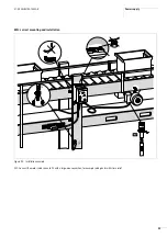
When the limit switch is reached, the drive switched off directly
through preprocessing of the RA-SP-HE… . PLC and bus cycle
times do not affect the power-off times.
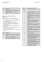
Interlocked manual mode can prevent damage to the conveyed
material and the plant in also manual operation.
If you have selected this function, limit switch I3 limits the possible
forward travel and limit switch I4 limits the possible reverse travel.
If the material reaches the limit switch in Manual mode, the drive
stops even if the selector switch remains in an actuating position.
In addition you can use this function to adjust the light barriers
before commissioning the PLC.
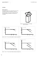
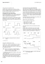
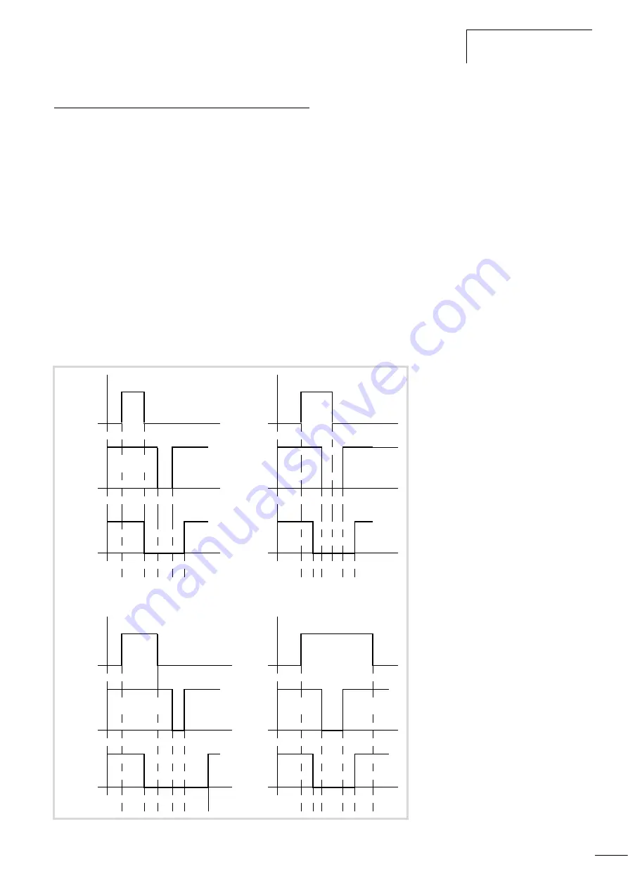
Quick stop with RA-SP-HE…
When the input signal is applied to pin 4 (rising edge), the RA-SP
switches the drive off. The input signal must be applied for at least
18.5 ms. As soon as the PLC output is reset (falling edge), the drive
can be switched on again. Whether the input signal is still applied
during the reset or during restarting of the PLC output has no
effect (
a
figure 114).
Sensors with break contacts can also be used. In this case the
speed control unit’s DIP switch must be set accordingly.
Figure 114: Quick stop in Automatic mode
(Example: I3 and forward rotation)
a
13.5 ms
g
5 ms
b
dependant upon PLC programme
I
3
I
3
O1
O1
(from PLC)
(from
PLC)
Signal at
actuation
Signal at
actuation
a
b a
a
b a
I
3
I
3
O1
O1
(from PLC)
(from
PLC)
Signal at
actuation
Signal at
actuation
a
b a
a
b
a
Summary of Contents for Rapid Link
Page 10: ...01 08 AWB2190 1430GB 6 ...
Page 40: ...01 08 AWB2190 1430GB 36 ...
Page 48: ...01 08 AWB2190 1430GB 44 ...
Page 70: ...01 08 AWB2190 1430GB 66 ...
Page 146: ...01 08 AWB2190 1430GB 142 ...
Page 162: ...01 08 AWB2190 1430GB 158 ...