background image

FX-TRN-BEG-E

Outline of the Lesson Plan 2

A-20

2.8

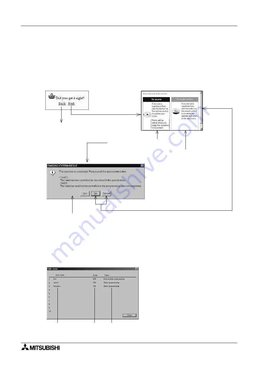
Self-judgement

If you are a registered user, the software will update your score whenever an exercise is
successfully completed.

In the final chapter of each exercise, a dialog box requests confirmation that the exercise
has been successfully completed. The user can judge whether the exercise has been
completed successfully or not.

The updated score can be confirmed by selecting "File" 

 "Display High Score" on the

simulation menu.

• Additional points are earned if you

complete the exercises repeatedly.

• The score can be deleted from the score

board selecting "File" 

 "Delete user

information" on the simulation menu.

If you are registered as a
user, click the [

!

] button on

the remote control.

In the final chapter

Self-judgement page

If you are not registered as
a user, click [Main] on the
remote control to return to
the menu screen.

Returns to the top
of the chapter.

Adds the score, and returns to the menu menu.
(If you are editing the ladder program, the message ’Do you want to save the ladder
program?’ is displayed as shown on the next page.)
The exercise button should have the ’good’ award and the ’number of times completed’
should be updated.

Return to the self-judgement page.

User 
name

Updated 
score

Class

Summary of Contents for MELSEC-F FX-TRN-BEG-E

Page 1: ...USER S MANUAL FX TRN BEG E Sections INTRODUCTION A EXERCISES B LADDER PROGRAMS C APPENDIX D ...

Page 2: ...FX TRN BEG E ...

Page 3: ...i FX TRN BEG E USER S MANUAL Manual number JY997D02901 Manual revision C Date April 2003 FX TRN BEG E ...

Page 4: ...FX TRN BEG E ii ...

Page 5: ...dom 01707 278 695 Please tick the box of your choice What condition did the manual arrive in Good Minor damage Unusable Will you be using a folder to store the manual Yes No What do you think to the manual presentation Tidy Unfriendly Are the explanations understandable Yes Not too bad Unusable Which explanation was most difficult to understand Are there any diagrams which are not clear Yes No If ...

Page 6: ...FX TRN BEG E iv ...

Page 7: ...egistration A 9 2 4 Configuration of Main Menu A 10 2 5 Configuration of Training Screen A 11 2 5 1 Training Screen A 11 2 5 2 3 D Virtual Manufacturing Cell A 12 2 5 3 Remote Control A 13 2 5 4 Ladder Program Area A 13 2 5 5 Guidance Window A 14 2 5 6 I O Image Table for Virtual PLC A 16 2 5 7 Operation Panel A 16 2 6 Writing a Program A 17 2 6 1 Preparation for Ladder Editing A 17 2 6 2 Reading ...

Page 8: ...FX TRN BEG E INTRODUCTION A 2 MEMO ...

Page 9: ...s to aid in the learning process The large number of exercises provide complete beginners and slightly more advanced users with challenges appropriate to each skill level Proceed through the exercises at the speed that is right for you The software setup and the flow of the lessons are explained in Chapter 2 Please read Chapter 2 to improve the effectiveness of the later lessons The 3 D graphic si...

Page 10: ...FX TRN BEG E Introduction 1 A 4 MEMO ...

Page 11: ...nstall the data from the CD ROM 2 2 Register as a User 2 3 Select a category in the main menu 2 4 or Exercise Section Select an exercise you would like to try 2 5 Read the guidance and understand the contents of the exercise 2 5 Write a program following the guidance 2 6 or Ladder Tool Section Transfer the program to the virtual PLC in your computer and confirm the machine operation 2 7 Judge the ...

Page 12: ...gistered trademarks of each company Operating Procedure 1 Start Windows and insert the CD SW0D5C FXTRN BEG E included in the package into the CD ROM drive to begin system installation It is recommended to end other application software before beginning the installation process OS Microsoft Windows 98 98SE Me Microsoft Windows NT4 0 SP3 or later Microsoft Windows 2000 Microsoft Windows XP 1 CPU Pen...

Page 13: ...xecuted the window shown below is displayed After reading and understanding the messages click Next Click Cancel to cancel installation 4 Select a folder for the installation destination If you wish to install it to the folder displayed click Next If you would like to change the folder click the Browse button to select the folder Click Cancel to cancel installation If the window is not displayed a...

Page 14: ...to start the installation 6 Complete the setup It takes about 10 seconds to perform installation If you take the CD out of the CD ROM drive or shut down your computer during installation the software will not install properly Click the Finish button to finish the setup Take out the CD and carefully store it for later use 7 Program folders are displayed When installation is completed the window sho...

Page 15: ...on the menu and points will be added to the user score Fill in the name and password fields to register for the first time Name Alphabetic and numeric 32 characters or less Password Numeric 8 characters or less If already registered as a user select the user name on the pull down menu and enter the password If the password does not match an error message will occur and the password must be re ente...

Page 16: ...egistered as a user the award is displayed on the exercise buttons that have been completed Category tabs good award Exercise button to jump to training screen Number of times the exercise has been completed Links to the outline of training software Your score The number of the stars indicates the difficulty level From which exercise shall we begin today ...

Page 17: ...n panels for simulation will be displayed automatically depending on the exercise Let s try to operate them correctly following the guidance Menu Bar Remote Control 2 5 3 Guidance Window 2 5 5 Minimizes the screen Fixes the screen display size Ends the training session 3 D Graphic Simulation Virtual Manufacturing cell window 2 5 2 Operation Panel 2 5 7 I O Image Table for monitoring RUN status in ...

Page 18: ... T S button on the remote control or selecting the direction on the Tools menu The device numbers are assigned to all the inputs and outputs of the machine as seen in the 3 D graphic simulation The I O list can be displayed selecting Edit I O list on the simulation menu The lists are also found on the pages in the EXERCISES section in this manual Example of I O list display Side view Front view To...

Page 19: ...itial condition Resets the simulation in case of unwanted occurrence such as parts are stuck takes place Initializes the virtual PLC Initializes outputs or devices The same operation as an actual PLC is switched from STOP to RUN mode Learning status display Indicates the status such as LEARN PROGRAM and RUN Main Displays the main menu or saves the program being edited and then displays the main me...

Page 20: ...idance display Title bar 2 5 3 You can move it to an arbitrary position by dragging the title bar using the mouse When it comes near a corner of the training software it is absorbed If the title bar is not displayed on the remote control select Tool Fix remote control bar from the tool menu then delete the check mark Example of hint page Example of first page in next chapter Chapter tabs Scroll ba...

Page 21: ... Click Main on the remote control to return to the main menu 1 Hint Scroll Update main the score and returns to the main menu Returns to the confirmation screen Note Did you get it right 2 Did you get it right 2 This box is not displayed if you are not registered as a user Click Yes to proceed to the next chapter Click No to return to the top of the chapter When Yes is clicked in the final chapter...

Page 22: ... O device numbers shown correspond to the ones on the specific virtual manufacturing cell Green indicates the RUN status Gray indicates the STOP status Red indicates the ON status Gray indicates the OFF status Lamp display Lit by outputs from the virtual PLC Operation switches Used to operate the machine in the simulation Switches Hold the ON or OFF status Turn ON and OFF with the mouse Pushbutton...

Page 23: ...e following operations are required in order to start ladder editing The PLC is in RUN mode immediately after the training screen is displayed Ladder editing cannot be performed in RUN mode 1 Click Edit Ladder on the remote control The status display is changed from RUN to PROGRAM 2 Click the Ladder Program Area or click Edit Ladder on the remote control to enable operation The title bar will turn...

Page 24: ...ple 1 to 5 on the simulation menu bar Up to five model answers are provided for each exercise You cannot select model answers displayed in gray Cautions If you edit a model answer and overwrite it the contents of the model answer are changed If you wish to edit a model answer file select Project Save As to create another model answer file with a different name for editing The contents of model ans...

Page 25: ...ance the operation speed of the machine simulation may be too high to realize the desired control If the message part does not stop in front of a sensor or the input data is not received properly is received select Tools Options on the ladder menu and reduce the speed The adjusted speed is remembered High on the scale bar means high speed Try the operation at medium speed If you choose the Simple ...

Page 26: ...lete the exercises repeatedly The score can be deleted from the score board selecting File Delete user information on the simulation menu If you are registered as a user click the button on the remote control In the final chapter Self judgement page If you are not registered as a user click Main on the remote control to return to the menu screen Returns to the top of the chapter Adds the score and...

Page 27: ... in the upper right corner of the screen or selecting File Exit on the simulation menu If you are editing the ladder program the dialog box below is displayed Saves the ladder program in a specified folder and exits the software Exits the software without saving the ladder program Cancels the operation ...

Page 28: ...FX TRN BEG E Outline of the Lesson Plan 2 A 22 MEMO ...

Page 29: ...sic I O Program Learn input and output programs 1 Indicator lamp 2 1 B 2 Standard Program Learn a latched output program and SET RST program 1 Indicator lamp 2 2 B 3 Control Precedence Program Learn an interlock program which controls conflicting operations 1 Traffic light with two signal lamps 2 3 B 4 Reading the Input Status Learn how to initiate instructions at the detection of rising or fallin...

Page 30: ...its size 2 Branch conveyor 5 2 E 3 Part Separation Give the command to a robot to move a part to a new location 2 Conveyor and unloading robot 5 3 E 4 Drilling Control the drill and other devices 2 Conveyor supply robot and drill 5 4 E 5 Part Supply Control Supply a specified number of parts according to the control specifications 3 Conveyor and supply robot 5 5 E 6 Conveyor Control Move the conve...

Page 31: ...A Let s Learn the FX Series PLC 1 B 3 1 A Let s Learn the FX Series PLC A 1 Introduction to the FX Series PLC A 2 Application Examples for the FX Series PLC A 3 Let s play a Little FX TRN BEG E ...

Page 32: ...Training Screen 1 1 2 Outline of Operation Click or to return to the previous screen or to go to the next screen Category A Let s Learn the FX Series PLC Exercise A 1 Introduction to the FX Series PLC Objective Study the introductory information Difficulty Level 1 Score Class 80 Basic programming ...

Page 33: ...versity Press Based on the above we can see that the word sequence indicates succession and the order in which they occur The meaning of the term sequence control is derived from the word sequence and indicates the control of operations in accordance with the predetermined order The word control indicates means by which a machine etc is operated or regulated Let s take a look at a familiar example...

Page 34: ...e control indicates let the sequence repeat automatically and correctly as many times as desired By using the PLC the door can be automatically opened and closed Control of automatic opening closing of the door using the PLC The car approaching the door is detected The loading bay door is opened Passage of the car is confirmed The loading bay door is closed Operation The In gate sensor turns ON Th...

Page 35: ...ttons Devices which indicate the machine status Such as sensors Devices which detect the machine status Such as lamps and buzzers Devices perform work Such as motors and solenoid valves Each of the input and output equipment is individually connected to the PLC The operation of each piece of equipment is determined by the sequence program in the PLC Control target classification In PLC control the...

Page 36: ...simulation are already wired to the virtual PLC Write a program confirming the control specifications indicated in the guidance with pre assigned input X and output Y device numbers The machines in the 3 D graphic simulation will operate according to downloaded program Various exercises are prepared in the software Try to solve them all PLC and peripheral I O equipment Learning screen ...

Page 37: ...cations The PLC is used for various purposes in various fields Let s look at various applications on the screen You should have seen the equipment operated by the PLC After confirming the application examples try to find various places in which use of the PLC is expected Category A Let s Learn the FX Series PLC Exercise A 2 Application Examples for the FX Series PLC Objective Look at the introduct...

Page 38: ...he introductory lessons Difficulty Level 1 Score Class 80 Introductory Basic Type Device No Device name Operation Input X0 Sensor ON when part is detected Conveyor is stopped Y0 Supply command One part is supplied when Y0 is ON A process cycle begins Output Y1 Conveyor forward Conveyor moves forward when Y1 is ON Y2 Pusher Extends when Y2 is ON and retracts when Y2 is OFF The pusher cannot be stop...

Page 39: ...he guidance and see how the PLC works Confirm that the operations change according to the programs The machines and the PLC on the screen are virtually simulated and are never damaged Don t hesitate to use them If you would like to learn the details of the key operations for the ladder programming refer to LADDER PROGRAMS in this manual ...

Page 40: ...FX TRN BEG E A Let s Learn the FX Series PLC 1 B 12 MEMO ...

Page 41: ...B Let s Study the Basics 2 B 13 2 B Let s Study the Basics B 1 Basic I O Program B 2 Standard Program B 3 Control Precedence Program B 4 Reading the Input Status FX TRN BEG E ...

Page 42: ... s Study the Basics Exercise B 1 Basic I O Program Objective Learn input and output programs Difficulty Level 1 Score Class 80 Basic programming Type Device No Device name Operation Output Y0 Operating lamp Green lamp is lit when Y0 is ON Y1 Stop lamp Yellow lamp is lit when Y1 is ON Y2 Error lamp Red lamp is lit when Y2 is ON ...

Page 43: ...so called internal relays are provided inside the PLC and their device symbol is represented by M Auxiliary relays are convenient when using dual OUT instructions and two or more contacts at a time Refer to the explanation in Section 3 Timer From T0 Timers are provided inside the PLC and their device symbol is represented by T Timers are used provide a set period of delay time before their nominat...

Page 44: ...n symbol Example of program See Chapter 1 in the guidance Reference Instruction word Inside the PLC contact symbols and Out instruction symbols are handled in instruction words NO contact Is normally open OFF and is closed turned ON when a signal is received from the input equipment NC contact Is normally closed ON and is opened turned OFF when a signal is received from the input equipment Is driv...

Page 45: ...ntact LD or LDI OR or NO contact connected in parallel to a contact LD or LDI ORI or inverse NC contact connected in parallel to a contact LD or LDI OUT out Coil drive instruction For the method to enter instruction words refer to the LADDER PROGRAMS section or to Appendix 1 X000 Y000 X002 Y000 X000 Y000 X002 or X000 M0 X002 M1 M0 Y000 M1 The output Y000 is controlled with both inputs X000 and X00...

Page 46: ...the Basics Exercise B 2 Standard Program Objective Learn a latched output program and SET RST program Difficulty Level 1 Score Class 80 Basic programming Type Device No Device name Operation Output Y0 Operating lamp Green lamp is lit when Y0 is ON Y1 Stop lamp Yellow lamp is lit when Y1 is ON Y2 Error lamp Red lamp is lit when Y2 is ON ...

Page 47: ...ed output instruction Enter another input condition X24 so that the route 1 and 2 are shut down and the latched output status is not operated X024 is an NC contact and normally ON When an input signal is given X024 is set OFF and the operation is stopped 2 Holding an output status using other methods Another instructions provided in the PLC can be used to easily hold the output status Example of S...

Page 48: ...ce Assignment Category B Let s Study the Basics Exercise B 3 Control Precedence Program Objective Learn a latched output program and SET RST program Difficulty Level 1 Score Class 80 Basic programming Type Device No Device name Operation Output Y0 Red signal Lit when Y0 is ON Y1 Green signal Lit when Y1 is ON ...

Page 49: ...t turn ON even if X025 turns ON B When X024 turns OFF Y000 is turned OFF Subsequently Y001 turns ON C As Y001 is set ON by X025 Y000 is not turned ON even if X024 turns ON 2 Interlock program in which precedence is given to the last input In the interlock program in example 1 outlines a precedence to the first input However the precedence can similarly be given to the input condition that has most...

Page 50: ...Level 2 Score Class 110 Basic programming Type Device No Device name Operation Input X0 Starting point ON when robot is at starting point X3 Sensor ON when part is detected Output Y0 Supply command One part is supplied when Y0 is ON A process cycle begins Y1 Conveyor forward Conveyor moves forward when Y1 is ON Y2 Conveyor reverse Conveyor moves backward when Y2 is ON Y3 Buzzer Sounds when Y3 is O...

Page 51: ...on switch which turns ON when pressed However because the PLF instruction is used here the OUT instruction M1 is operated on the falling edge of input X020 for a single scan cycle Even if inputs X024 or X020 are set ON or OFF by the PLS or PLF instruction the latched output instruction program for Y000 Y001 and Y006 can be shut down by the input of X021 2 Contact type rising falling edge detection...

Page 52: ...FX TRN BEG E B Let s Study the Basics 2 B 24 MEMO ...

Page 53: ...C Easy Does It 3 B 25 3 C Easy Does It C 1 Base of timer circuit C 2 Application of timer circuit 1 C 3 Application of timer circuit 2 C 4 Base of counter circuit FX TRN BEG E ...

Page 54: ... time function Difficulty Level 1 Score Class 80 Basic programming Type Device No Device name Operation Input X0 Lower limit ON when door reaches lower limit X1 Upper limit ON when door reaches upper limit Output Y0 Door up command Door moves up when Y0 is ON Y1 Door down command Door moves down when Y1 is ON Y5 Red Lit when Y5 is ON Y6 Green Lit when Y6 is ON Y7 Yellow Lit when Y7 is ON ...

Page 55: ...et value B the current value becomes constant and the timer contact turns ON C When the input to operate the timer is turned OFF the timer contact is also OFF and the current value is cleared D How to determine the set value depends on the device number Refer to the Appendix For example T0 is the time with the base time 100ms 0 1 sec If the set value is K30 the operation starts after 3 seconds bec...

Page 56: ... function and the one shot timer Difficulty Level 1 Score Class 80 Basic programming Type Device No Device name Operation Input X0 Lower limit ON when door reaches lower limit X1 Upper limit ON when door reaches upper limit Output Y0 Door up command Door moves up when Y0 is ON Y1 Door down command Door moves down when Y1 is ON Y5 Red Lit when Y5 is ON Y6 Green Lit when Y6 is ON Y7 Yellow Lit when ...

Page 57: ...021 is turned ON instantaneously by the rising edge detection instruction Even if the input of X021 is kept ON the contact turns OFF The latched output instruction enables Y006 and T2 to remain ON as indicated in line B After the set time of the timer T2 elapses K50 5 sec C turns OFF and then the OUT instruction Y006 and T2 are turned OFF 3 Lighting the lamps using timers When the switch X020 is s...

Page 58: ...2 Device Assignment Category C Step Up Exercise C 3 Application Timer Program 2 Objective Learn a flicker program executed by timers Difficulty Level 2 Score Class 110 Basic programming Type Device No Device name Operation Output Y0 Red signal Lit when Y0 is ON Y1 Green signal Lit when Y1 is ON ...

Page 59: ...001 and T4 turn ON as indicated in line C Four seconds later set value of K40 in T4 the contact D turns OFF and thus T3 turns OFF as indicated in line A While X024 is ON Y001 repeats an OFF for 2 seconds and ON for 4 seconds cycle 2 Flickering the signal lamps In the program above Y001 flickers OFF for 2 seconds and ON for 4 seconds while the switch X024 is ON T3 T4 C Y001 B C X024 T3 A T4 D K20 K...

Page 60: ...nters Difficulty Level 2 Score Class 110 Basic programming Type Device No Device name Operation Input X0 Sensor ON when part is detected at the right end Output Y0 Supply command Indicator on screen is lit when Y0 is ON Operator supplies parts while indicator is lit Y1 Conveyor forward Conveyor moves forward when Y1 is ON Y3 Red Lit when Y3 is ON Y4 Green Lit when Y4 is ON Y5 Yellow Lit when Y5 is...

Page 61: ...ounter turns ON B After the counter reaches the set value the current value is not changed even if the count input C is set ON and OFF and the counter contact remains ON B When the counter reset instruction RST is set ON the current value of the counter becomes 0 D and the contact turns OFF While the RST instruction is ON any count input is not counted E When the RST instruction is set OFF count i...

Page 62: ...he counter is reset by input X001 Minor Addition Let s stop the supply of parts when the current value of the counter reaches the set value K10 Include a NC contact for the counter to line a above Let s supply parts only while the conveyor is moving Include a NC contact for the conveyor operation Y001 to line a above X002 Y000 X000 C0 a X003 X001 C0 RST Y001 C0 Y006 K10 b c d e X002 Y000 C0 Add th...

Page 63: ...eginner Challenge 4 B 35 4 D Beginner Challenge D 1 Paging Unit D 2 Detect Sensor Light D 3 Time Control for Traffic Light D 4 Part Sorting by Size I D 5 Conveyor Start Stop D 6 Conveyor Drive FX TRN BEG E ...

Page 64: ...allenge Exercise D 1 Paging Unit Objective Control the paging unit in a restaurant Difficulty Level 1 Score Class 130 Beginner programming Type Device No Device name Operation Input X0 Button 1 Momentary ON OFF mouse click X1 Button 2 Momentary ON OFF mouse click Output Y0 Lamp 1 Lit when Y0 is ON Y1 Lamp 2 Lit when Y1 is ON ...

Page 65: ... pressed Lamp 1 Y0 on the wall is lit If Button 1 X0 is released Lamp 1 Y0 remains lit 2 When Button 2 X1 is pressed Lamp 2 Y1 on the wall is lit If Button 2 X1 is released Lamp 2 Y1 remains lit 3 When both Lamp 1 Y0 and Lamp 2 Y1 are lit PL4 Y23 on the operation panel lights 4 When PB1 X20 on the operation panel is pressed both Lamp 1 Y0 and Lamp 2 Y1 on the wall and PL4 Y23 on the operation pane...

Page 66: ...Beginner programming Type Device No Device name Operation Input X0 In gate person ON when person is detected X1 Out person ON when person is detected X2 In gate car ON when car is detected X3 Out car ON when car is detected Output Y0 Red person Lit when Y0 is ON Y1 Green person Lit when Y1 is ON Y2 Yellow person Lit when Y2 is ON Y3 Red car Lit when Y3 is ON Y4 Green car Lit when Y4 is ON Y5 Yello...

Page 67: ... Out X1 detects the passage of the person the flashing light Green Y1 is extinguished Car side 1 When the sensor In gate X2 detects a car the flashing light Green Y4 is lit 2 5 seconds after the sensor Out X3 detects the passage of the car the flashing light Green Y4 is extinguished 3 If the car does not pass through the area between In gate X2 and Out X3 within 10 seconds the flashing light Red Y...

Page 68: ...Beginner Challenge Exercise D 3 Time Control for Traffic Light Objective Control a traffic light where the signals are changed at specified time intervals Difficulty Level 2 Score Class 160 Beginner programming Type Device No Device name Operation Output Y0 Red Lit when Y0 is ON Y1 Yellow Lit when Y1 is ON Y2 Green Lit when Y2 is ON ...

Page 69: ...l is pressed the process is started 2 First the signal lamp Red Y0 is lit for 10 seconds 3 he signal lamp Red Y0 is extinguished after it has been lit for 10 seconds The signal lamp Yellow Y1 is lit for 5 seconds 4 The signal lamp Yellow Y1 is extinguished after it has been lit for 5 seconds The signal lamp Green Y2 is lit for 10 seconds 5 The signal lamp Green Y2 is extinguished after it has been...

Page 70: ...lty Level 2 Score Class 160 Beginner programming Type Device No Device name Operation Input X0 Upper ON when part is detected X1 Middle ON when part is detected X2 Lower ON when part is detected X4 Sensor ON when part is detected at the right end X5 Starting point ON when robot is at starting point Output Y3 Conveyor forward Conveyor moves forward when Y3 is ON Y5 Supply command One part is suppli...

Page 71: ...d OFF 2 When Operation start X14 on the operation panel is turned ON Conveyor forward Y3 is ON When Operation start X14 on the operation panel is turned OFF Conveyor forward Y3 is OFF 3 Large medium or small parts carried on the conveyor are sorted by the input of sensors Upper X0 Middle X1 or Lower X2 then a corresponding lamp is lit Large Y10 Medium Y11 Small Y12 4 A lamp is lit immediately afte...

Page 72: ...ner programming Type Device No Device name Operation Input X0 Starting point ON when robot is at starting point X3 Sensor ON when part is detected at the right end Output Y0 Supply command One part is supplied when Y0 is ON A process cycle begins Y1 Conveyor forward Conveyor moves forward when Y1 is ON Y2 Conveyor reverse Conveyor moves backward when Y2 is ON Y3 Buzzer Sounds when Y3 is ON Lamp on...

Page 73: ... Y7 is lit and Buzzer Y3 sounds for 5 seconds If PB1 X20 is released Yellow Y7 remains lit 2 After the flashing light Yellow Y7 is extinguished and Buzzer Y3 stops Conveyor forward Y1 is set ON The flashing light Green Y6 remains lit while the Conveyor forward Y1 is ON 3 When PB2 X21 on the operation panel is pressed the operations described in 1 and 2 stop The operations should be repeated when t...

Page 74: ...veyor according to the sensor data Difficulty Level 2 Score Class 160 Beginner programming Type Device No Device name Operation Input X0 Sensor ON when part is detected at the left end X1 Sensor ON when part is detected at the left end X2 Sensor ON when part is detected at the left end X3 Sensor ON when part is detected at the right end X5 Starting point ON when robot is at starting point ...

Page 75: ... part Lower conveyor forward Y4 is set ON and Middle conveyor forward Y2 stops 5 When Sensor X3 detects a part Lower conveyor forward Y4 stops 6 When Sensor X3 is set ON Supply command Y7 for the robot is turned ON and a new part is supplied if the robot is at Starting point X5 Output Y0 Upper conveyor forward Conveyor moves forward when Y0 is ON Y1 Upper conveyor reverse Conveyor moves backward w...

Page 76: ...FX TRN BEG E D Beginner Challenge 4 B 48 MEMO ...

Page 77: ...E Intermediate Challenge 5 B 49 5 E Intermediate Challenge E 1 Pushbutton Signal E 2 Part Sorting by Size II E 3 Part Separation E 4 Drilling E 5 Part Supply Control E 6 Conveyor Control FX TRN BEG E ...

Page 78: ...tegory E Intermediate Challenge Exercise E 1 Pushbutton Signal Objective Switch the traffic light signals in response to a pushbutton Difficulty Level 2 Score Class 210 Intermediate programming Type Device No Device name Operation Output Y0 Red Lit when Y0 is ON Y1 Yellow Lit when Y1 is ON Y2 Green Lit when Y2 is ON ...

Page 79: ...10 is released the indicator Y10 remains lit 3 After the indicator Y10 is lit for 5 seconds the operation of the signal is changed as described in 4 to 7 4 First the signal lamp Red Y0 flickers for 5 seconds while indicator Y10 is lit 5 The signal lamp Red Y0 turns off The signal lamp Yellow Y1 is lit for 5 seconds 6 After the lamp Yellow Y1 is extinguished signal lamp Green Y2 is lit for 10 secon...

Page 80: ...tion Input X0 Starting point ON when robot is at starting point X1 Upper ON when part is detected X2 Middle ON when part is detected X3 Lower ON when part is detected X4 Sensor ON when part is detected at the right end X5 Sensor ON when part is detected at the right end Output Y0 Supply command One part is supplied when Y0 is ON A process cycle begins Metal cylinder repeats in order L S S L and S ...

Page 81: ...OFF the conveyors stop 2 When PB1 X20 on the operation panel is pressed Supply command Y0 for the robot is turned ON Supply command Y0 is turned OFF when the robot has moved from the starting point The robot will complete the part loading cycle 3 The robot supplies large medium or small parts 4 Large parts are led to the rear conveyor and small parts are led to the front conveyor The part size is ...

Page 82: ...210 Intermediate programming Type Device No Device name Operation Input X0 Starting point ON when robot is at starting point X1 Part on table ON when part is on table X2 Robot operation finished ON when robot operation finished Output Y0 Supply command Indicator on screen is lit when Y0 is ON Operator supplies parts while indicator is lit Y1 Conveyor forward Conveyor moves forward when Y1 is ON Y2...

Page 83: ...ard 3 When PB1 X20 on the operation panel is pressed Supply command Y0 is turned ON and the Supply allowed indicator lamp is lit The operator supplies a part When PB1 X20 is released the indicator lamp is extinguished However if a part is still located on the table Supply command Y0 is not turned ON so that the indicator lamp Supply allowed is not lit 4 When Part on table X1 is turned ON in the ro...

Page 84: ...der drill ON when part is under the drill X2 Drilled correctly ON when part is drilled correctly Previous result is cleared when drilling starts X3 Drilled wrong ON when part is not drilled correctly Previous result is cleared when drilling starts X5 Sensor ON when part is detected at the right end Output Y0 Supply command One part is supplied when Y0 is ON A process cycle begins Large metal cube ...

Page 85: ... conveyor stops Control of drill 1 When the sensor for Part under drill X1 in the drill is turned ON the conveyor stops 2 When Start drilling Y2 is turned ON the drilling starts Start drilling Y2 is turned OFF when Drilling X0 is set ON 3 When Start drilling Y2 is turned ON either Drilled correctly X2 or Drilled wrong X3 is set ON after the drill machine has operated for one complete cycle The dri...

Page 86: ...240 Intermediate programming Type Device No Device name Operation Input X0 Starting point ON when robot is at starting point X1 Box on conveyor ON when box is under orange feeder X2 Orange supplied ON when orange is detected for counting X5 Sensor ON when part is detected at the right end Output Y0 Supply command One part is supplied when Y0 is ON A process cycle begins Large box Y1 Conveyor forwa...

Page 87: ...s pressed Supply command Y0 for the robot is turned ON Supply command Y0 is turned OFF when the robot has moved from the starting point When Supply command Y0 is turned ON the robot supplies a box Control of oranges 1 When the sensor for Box on conveyor X1 in the orange feeder is turned ON the conveyor stops 2 Five oranges are placed in the box Boxes containing 5 oranges are carried to the tray at...

Page 88: ...s Difficulty Level 3 Score Class 240 Intermediate programming Type Device No Device name Operation Input X10 Left limit ON when part is detected at the left end X11 Right limit ON when part is detected at the right end X12 Stop sensor ON when part is detected Output Y10 Supply command One part is supplied when Y10 is ON A process cycle begins Y11 Conveyor forward Conveyor moves forward when Y11 is...

Page 89: ...per supplies a part 2 When PB2 X21 on the operation panel is pressed the conveyor is operated in a sequence as described in 3 to 6 below If PB2 X21 is released the sequence of operation continues 3 The conveyor starts moving when Conveyor forward Y11 is set ON and stops when Right limit X11 for the part is turned ON 4 The conveyor moves in reverse when Conveyor reverse Y12 is set ON until Left lim...

Page 90: ...FX TRN BEG E E Intermediate Challenge 5 B 62 MEMO ...

Page 91: ...B 63 6 F Advanced Challenge F 1 Automatic Door Operation F 2 Stage Settings F 3 Part Distribution F 4 Sorting Defective Parts F 5 Forward Reverse Rotation Control F 6 Lifter Control F 7 Sorting Distribution Line FX TRN BEG E ...

Page 92: ...ect Difficulty Level 3 Score Class 290 Advanced programming Type Device No Device name Operation Input X0 Lower limit ON when door reaches lower limit X1 Upper limit ON when door reaches upper limit X2 In gate sensor ON when object approaches the door X3 Out sensor ON when object leaves the door Output Y0 Door up Moves up when Y0 is ON Y1 Door down Moves down when Y1 is ON Y6 Light Lit when Y6 is ...

Page 93: ...ops moving down when Lower limit X0 is turned ON 5 While the car is still in the detection range between In gate sensor X2 and Out sensor X3 the door will not move down 6 Buzzer Y7 sounds while the door is in motion 7 Light Y6 is lit while the car is in the detection range between In gate sensor X2 and Out sensor X3 8 Four indicator lamps on the operation panel are lit or extinguished according to...

Page 94: ...g Type Device No Device name Operation Input X0 Inside Left curtain ON when curtain closes completely X1 Middle Left curtain ON when curtain is halfway X2 Outside Left curtain ON when curtain opens completely X3 Inside Right curtain ON when curtain closes completely X4 Middle Right curtain ON when curtain is on its half way X5 Outside Right curtain ON when curtain opens completely X6 Stage upper l...

Page 95: ...ration described above is not in operation 2 The curtains can be opened only while Curtain open X10 on the operation panel is being pressed The curtains stop at their outward limits X2 and X5 3 The curtains can be closed only while Curtain close X11 on the operation panel is being pressed The curtains close until their inward limits X0 and X3 4 The stage can be moved up only while Stage up X12 on ...

Page 96: ...ut X0 Starting point ON when robot is at starting point X1 Upper ON when part is detected X2 Middle ON when part is detected X3 Lower ON when part is detected X4 Sensor ON when part is detected on the incline X5 Sensor ON when part is detected on the incline X6 Sensor ON when part is detected on the incline X7 Sensor ON when part is detected at the right end X10 Detect part ON when part is detecte...

Page 97: ...pusher is set ON it extends completely When the actuating command is set OFF the pusher retracts 5 The following number of parts for each size are to be placed in the trays Excess parts are to pass in front of the pushers and fall from the right end Large 3 parts Medium 2 parts Small 2 parts Output Y0 Supply command One part is supplied when Y0 is ON A process cycle begins Wooden part repeats in o...

Page 98: ...ming Type Device No Device name Operation Input X0 Drilling ON while drilling X1 Part under drill ON when part on conveyor is detected by drill X2 Drilled correctly ON when part is drilled correctly Previous result is cleared when drilling starts X3 Drilled wrong ON when part is not drilled correctly Previous result is cleared when drilling starts X4 Sensor ON when part is detected at the left end...

Page 99: ... set ON after the drill machine has operated for one complete cycle The drill cannot be stopped in the middle of an operation In this simulation one out of three parts is to be a defective part When multiple holes are drilled on a part it is also a defective part 4 When a defective part is detected by Detect part X10 in the pusher the conveyor stops and the pusher pushes it onto the Defective tray...

Page 100: ...evice name Operation Input X0 Upper ON when part is detected X1 Middle ON when part is detected X2 Lower ON when part is detected X3 Detect part ON when part is detected in front of pusher X4 Starting point ON when robot is at starting point X5 Part on table ON when part is on table X6 Robot operation finished ON when robot operation finished X7 Sensor ON when part is detected on the incline X10 S...

Page 101: ... pushed to the lower conveyor Note When the actuating command for the pusher is set ON it extends completely When the actuating command is set OFF the pusher retracts completely 5 When Part on table X5 is turned ON in the robot Unload command Y4 is set ON When Robot operation finished X6 is turned ON it is ON when a part is placed on the tray Unload command Y4 is set OFF 6 While SW2 X25 on the ope...

Page 102: ...ected X2 Lower ON when part is detected X3 Part on lift ON when part is on the lift X4 Lower lift position ON when the lift is at lower position X5 Middle lift position ON when the lift is at middle position X6 Upper lift position ON when the lift is at upper position X10 Sensor ON when part is detected at the left end X11 Sensor ON when part is detected at the right end X12 Sensor ON when part is...

Page 103: ... carried to either of the following conveyors according to its size Large part Upper conveyor Medium part Medium conveyor Small part Lower conveyor 2 Lift up command Y2 and Lift down command Y3 are controlled according to the lift position detected by the following sensors Upper X6 Meddle X5 Lower X4 3 When a part is transferred from the lift to the conveyor Lift rotation command Y4 is set ON 4 Af...

Page 104: ...vice name Operation Input X0 Starting point Supply ON when supplying robot is at start point X1 Upper ON when part is detected X2 Middle ON when part is detected X3 Lower ON when part is detected X4 Sensor ON when part is detected at the right end X5 Sensor ON when part is detected at the right end X6 Detect part ON when part is detected in front of pusher X10 Starting point Unload ON when unloadi...

Page 105: ...yor stops and the part is pushed onto the tray 4 When Part on table X11 is turned ON in the robot Unload command Y7 is set ON When Robot operation finished X12 is turned ON it is ON when a part is placed on the tray Unload command Y7 is set OFF 5 While SW2 X25 on the operation panel is ON a new part is to be automatically supplied at the following time When the robot starts to carry a medium part ...

Page 106: ...FX TRN BEG E F Advanced Challenge 6 B 78 MEMO ...

Page 107: ...ject with a Different Name C 6 2 2 3 Overwriting of a project C 6 2 3 Opening a project C 7 2 4 Copying a project C 8 3 Operation C 9 3 1 Writing the program C 10 3 1 1 Basic instruction C 10 3 1 2 Writing STL Instruction C 13 3 1 3 Application instruction C 14 3 1 4 Conversion C 15 3 2 Editing the Program C 16 3 2 1 Insert and Delete C 16 3 2 2 Cut Copy and Paste C 17 3 2 3 Undo C 18 3 3 Display ...

Page 108: ... simulation the ladder program area and the operation panel This section explains how to use the ladder Click Edit Ladder on the remote control to activate the ladder program area Refer to 3 4 3 D graphic simulation Virtual PLC Guidance Operation panel Ladder program area Remote control ...

Page 109: ...dder tool In the ladder program creates area you write edit and monitor ladder programs Machines in the simulation are operated by the ladder programs you create here Programming Device test Monitoring ON Writing Virtual PLC Program Program ON ...

Page 110: ...FX TRN BEG E Outline 1 C 4 MEMO ...

Page 111: ...at is a Project A project consists of programs and device comments 2 2 Creating and Saving Project 2 2 1 Creating a new project 1 Select Project New project 2 A new project is created Item Description Program Program to operate the CPU of the PLC Device comment Comment on device Project Programs Device comments When a new project is created the screen displays this FX TRN BEG E ...

Page 112: ...header then click the Save button 2 2 3 Overwriting of a project 1 Select Project Save 2 The open project is overwritten with the contents displayed on the screen When Save is selected for the first time since the project is created the Save as dialog box is displayed in the same way as explained above Specify the place in which the project is saved Enter the project name Enter the header ...

Page 113: ...layed select a project to open You can open only one project at a time If you try to open another project while editing a project the message is displayed asking if you want to save it POINT For reading and handling of model answers refer to the Introduction Section in this manual Select a project The place in which the project is located is displayed The selected project name is displayed ...

Page 114: ...isplayed 2 Select a source file and the data to be copied then click the Execute button Source file Programs Device comments Project being edited Programs Device comments Click the Browse button then select a source file The drive path name and the project name of the source file are displayed Coose the data to be copied If you click the Execute button without choosing anything an error message is...

Page 115: ...ual PLC You can monitor how the program is executed in the virtual PLC 3 4 1 Writing to PLC 3 4 2 Monitor display Virtual PLC Program Program You can set devices ON and OFF write values confirm the operation of the program 3 4 3 Device test You can write and convert programs and enter device comments 3 1 Writing the program 3 2 Editing the program 3 3 Displaying and entering comments FX TRN BEG E ...

Page 116: ...sic instruction specify a symbol pressing a function key the device number and the set value How to write NO contact 1 Place the cursor where you write an NO contact 2 Press the F5 key The Enter symbol dialog box is displayed 3 Type a device and click the OK button NO contact is written After the program is written the background is displayed in gray Check the current mode here Program capacity 80...

Page 117: ... TRN BEG E Operation 3 C 11 POINT If you write a program placing a cursor on a program symbol already written the results differ as shown below depending on the mode Input Input Overwrite mode Insert mode ...

Page 118: ... contact data can be changed You can input basic instructions not only by pressing the function keys but also by typing letters For its method refer to the Appendix 1 2 F7 Y0 OUT instruction F7 T0 K50 Timer F7 C0 K20 Counter F8 SET Y1 SET F8 PLS M1 PLS F6 Y0 NO contact OR Shift F9 Vertical line 1 F9 Horizontal line 1 F8 XXXX Function key Characters to type Shift X1 F5 NC contact 1 Type a number fo...

Page 119: ...g the RET instruction 1 Draw a vertical line from the STL symbol and place the cursor where the RET instruction is to be written 2 Press the F8 key The Enter symbol dialog box is displayed 3 Type RET 4 Click the OK button Both capital letters and small letters can be used Type the state number Write the RET instruction after drawing a vertical line from the STL instruction Both capital letters and...

Page 120: ...Enter symbol dialog box is displayed Type MOV K100 D0 2 Click the OK button Write the MOVP instruction and the DMOVP instruction as follows LD instruction 1 Place the cursor where the LD instruction is to be written Press the F8 key The Enter symbol dialog box is displayed Type LD K100 D20 2 Click the OK button POINT For the list of available instructions and input procedures refer to the Appendix...

Page 121: ...t them 1 After writing the programs press the F4 key 2 The programs are converted The background of the programs should be displayed in white If there is an incorrect program an error message is displayed and the part is displayed in yellow Correct the program POINT Programs you write are determined when they are converted An incorrect program is displayed in yellow ...

Page 122: ...he cursor position Deleting contacts Delete a contact pressing the Delete or Back space key The result displayed on the screen differs depending on the mode as shown below The contact in the cursor position is deleted and the position becomes blank The contact on the left side of the cursor position is deleted and the position becomes blank Delete Back space Overwrite mode Insert mode The contact ...

Page 123: ...ontal line press the Shift keys to move the cursor When deleting a vertical line press the Shift keys to move the cursor 3 When you release the Shift key a horizontal or vertical line is deleted POINT Only horizontal and vertical lines can be deleted using this method Even if you operate the above explained procedure on a contact the contact is not deleted 3 2 2 Cut Copy and Paste The method to cu...

Page 124: ...ing those operations select Edit Undo You can undo up to ten operations However you cannot delete comments by Undo Return to the status after circuit conversion You can delete the programs currently being edited and return to the status immediately after the previous conversion 1 A program is edited 2 Select Edit Restore after ladder conversion When the confirmation dialog box is displayed click Y...

Page 125: ... View Comment 2 Comments are displayed Changing the number of characters for device comments You can select the number of characters of each displayed device comment between 16 and 32 When changing the number of displayed characters follow the below procedure 1 Select Tools Options 2 When the Options dialog box is displayed select 16 or 32 at Show device comment Device comment Select the number of...

Page 126: ...vailable You cannot delete a comment selecting Undo POINT You can type device comments when you are writing an instruction 1 Select Tools Options 2 When the Options dialog box is displayed specify Continues during instruction write Enter an instruction and comment as follows Double click on the coil Type a comment up to 32 characters The device number for the comment If you specify it you can type...

Page 127: ...LC dialog box is displayed and you can check the writing status there If the virtual PLC is in RUN mode it is automatically and writing is executed 3 When writing is completed the dialog box Write completed The simmulation will start is displayed Click the OK button to run the virtual PLC POINT Status display of the virtual PLC and Write to PLC on the remote control Write to PLC Program Virtual PL...

Page 128: ...e displayed in the selected display format The present values are displayed in real numbers if the instructions take real numbers 3 4 3 Device test During monitoring you can confirm the program operation by setting devices to ON or OFF and changing the present values 1 Select Online Devece Test 2 When the Device Test dialog box is displayed type the device number to the Device field Bit device OFF...

Page 129: ...executed the machines simulated and the operation panel in which the same device is set are also affected in the same way Type the device number whose value is to be changed After specifying the value click the set button The value will be set for the selected device Enter the device number to be changed Specify decimal or hexadecimal Specify 16 bit integer 32 bit integer or real number then type ...

Page 130: ...as shown below POINT All the programs are printed If printing is executed during monitoring the contents of the monitor display are also printed Display in ladder program area Printing result Each device comment is displayed in up to 16 characters Each device comment is printed in up to 16 characters Each device comment is displayed in up to 32 characters Each device comment is printed in up to 32...

Page 131: ... Initial logical operation Falling trailing edge pulse Shift F8 X0 LDF_X0 AND AND Serial connection of NO normally open contacts F5 X0 AND_X0 ANI AND Inverse Serial connection of NC normally closed contacts Shift F5 X0 ANI_X0 ANP ANd Pulse Serial connection of Rising edge pulse Shift F7 X0 ANDP_X0 ANF ANd Falling pulse Serial connection of Falling trailing edge pulse Shift F8 X0 ANDF_X0 OR OR Para...

Page 132: ...trailing edge pulse F8 PLF_X0 PLF_X0 MC Master Control Denotes the start of a master control block F8 MC_N0_X0 MC_N0_X0 MCR Master Control Reset Denotes the end o a master control block F8 MCR_N0 MCR_N0 MPS Master Point Store Stores the current result of the internal PLC operations MRD Master ReaD Reads the current result of the internal PLC operations MPP Master PoP Pops recalls and removes the c...

Page 133: ...adder instructions _ underline Leave a space here Mnemonic Function Input method Symbol Input method Instruction Program and target device STL STep Ladder Starts stepladder F8 STL_S0 STL_S0 RET RETurn Ends stepladder F8 RET RET ...

Page 134: ...CML Compliment 15 BMOV Block Move 16 FMOV Fill Move 17 XCH Exchange 18 BCD Binary Coded Decimal 19 BIN Binary Four rules Logical operation 20 ADD Addition 21 SUB Subtraction 22 MUL Multiplication 23 DIV Division 24 INC Increment 25 DEC Decrement 26 WAND Word AND 27 WOR Word OR 28 WXOR Word Exclusive OR 29 NEG Negation Rotation shift 30 ROR Rotation Right 31 ROL Rotation Left 32 RCR Rotation Right ...

Page 135: ...p Variable Value 69 SORT Sort Data External equipment I O 76 ASC ASCII Code 78 FROM Read From A Special Function Block 79 TO Write To A Special Function Block External equipment SER 82 ASCI Hexadecimal to ASCII 83 HEX ASCII to Hexadecimal Floating decimal point 110 ECMP Float Compare 111 EZCP Float Zone Compare 118 EBCD Float to Scientific 119 EBIN Scientific to Float 120 EADD Float Add 121 ESUB F...

Page 136: ...0 GRY Decimal to Gray Code 171 GBIN Gray Code to Decimal Contact comparison 224 LD LoaD compare 225 LD LoaD compare 226 LD LoaD compare 228 LD LoaD compare 229 LD LoaD compare 230 LD LoaD compare 232 AND AND compare 233 AND AND compare 234 AND AND compare 236 AND AND compare 237 AND AND compare 238 AND AND compare 240 OR OR compare 241 OR OR compare 242 OR OR compare 244 OR OR compare 245 OR OR co...

Page 137: ... Auxiliary relays M General M0 to M512 512 Special M8000 to M8255 256 State relays S Initial S0 to S9 10 General S10 to S511 502 Word devices Timers T 100ms T0 to T199 200 10ms T200 to T245 46 1ms retentive 1 T246 to T249 4 100ms retentive 1 T250 to T1255 6 Counters C 16 bit up C0 to C T199 200 32 bit up down C200 to C234 35 Data registers D Pair for 32 bit device General D0 to D511 512 Latched D8...

Page 138: ...n negative number M8022 Carry Set when carry occurs during an ADD FNC 20 or when an overflow occurs as a result of a data shift operation M8024 BMOV reverse mode ON Write OFF Read M8026 RAMP hold mode ON Hold output value OFF Reset output value M8029 Instruction execution complete OFF Executing ON Execution complete M8031 Non latch memory all clear OFF Hold ON Clear M8033 Memory hold in stop mode ...

Page 139: ...0 functions as a down counter OFF C200 functions as an up counter M8201 Up Down Counter Control ON C201 functions as a down counter OFF C201 functions as an up counter M8202 Up Down Counter Control ON C202 functions as a down counter OFF C202 functions as an up counter M8203 Up Down Counter Control ON C203 functions as a down counter OFF C203 functions as an up counter M8204 Up Down Counter Contro...

Page 140: ...ounter OFF C222 functions as an up counter M8223 Up Down Counter Control ON C223 functions as a down counter OFF C223 functions as an up counter M8224 Up Down Counter Control ON C224 functions as a down counter OFF C224 functions as an up counter M8225 Up Down Counter Control ON C225 functions as a down counter OFF C225 functions as an up counter M8226 Up Down Counter Control ON C226 functions as ...

Page 141: ...th an RTC 00 99 or 1980 2079 can be selected 2 D8019 Weekday data D8028 Current value of the Z0 index register Current value of the Z0 index register D8029 Current value of the V0 index register Current value of the V0 index register D8040 Lowest active STL step Lowest active STL step D8041 2nd active STL state 2nd active STL state D8042 3rd active STL state 3rd active STL state D8043 4th active S...

Page 142: ...Z3 index register Value of Z3 index register D8187 Value of V3 index register Value of V3 index register D8188 Value of Z4 index register Value of Z4 index register D8189 Value of V4 index register Value of V4 index register D8190 Value of Z5 index register Value of Z5 index register D8191 Value of V5 index register Value of V5 index register D8192 Value of Z6 index register Value of Z6 index regi...

Page 143: ...ow signal lamps light Rotating beacon Red green and yellow flashing lights light Machine Conveyor standard type Conveyor carries parts Output must be driven C 5 Conveyor branch type Conveyor distributes parts into two directions Lifter Lifter carries parts to upper and lower positions Door Door is opened and closed vertically Pusher Pusher pushes out parts Drill Drill makes holes in parts Stage se...

Page 144: ...sor detects the passage and contact of a part Appearance side view Operation A sensor is assigned to an input X When an object such as a part passes a sensor the corresponding input turns ON To rear To right To left To front ON OFF OFF ON ...

Page 145: ... the output Y is set ON the robot starts to supply a part Even if the driving output for the robot is set OFF while it is supplying a part the robot continues the operation until it places the part on the conveyor Even if the next supply command is given to the robot while it is supplying a part the robot does not accept the command Make sure to give the command to the robot while the starting poi...

Page 146: ...hey will be crushed Hopper Part Conveyor Appearance side view Operation Orange supply command As an orange supply command an output Y is assigned When the supply command output Y is set ON oranges are continuously supplied Box detection sensor This sensor turns ON when it detects a box under the feeder NO contact This sensor is built in the feeder and is not displayed Orange passage sensor The inp...

Page 147: ...graphic mode The 3 D graphic would not be displayed properly Red Green Appearance Operation An individual output Y is assigned to each of red green and yellow lamp Each lamp is lit when the output is ON and extinguished when the output is OFF Mechanical interlock is not provided between the three lamps The three lamps can be lit at the same time Do not specify the Simple graphic mode The 3 D graph...

Page 148: ... reverse command An output Y is assigned to each of forward and reverse movement When the output Y is set to ON the conveyor moves In some exercises an output Y is assigned to either normal or reverse movement Reverse Forward Sensor Sensor Indicator for forward rotation Indicator for reverse rotation Appearance side view Operation Conveyor operation command An output Y is assigned to the conveyor ...

Page 149: ...yed The mechanical interlock between the up and down movements of the lifter is provided inside the machine simulation If both inputs are ON at the same time the lifter is not damaged but neither does it move Appearance side view Appearance front view Conveyor Conveyor Part Lifter The lifter moves up 2 1 Part absence presence detection sensor not displayed Lifter moving up down motors not displaye...

Page 150: ...t If the setting is incorrect the lifter may rotate to a spot where no conveyor is available The part may fall down or become stuck C 5 4 Door The door is opened and closed vertically Example Displayed in red while the sensor is ON Sensor X000 Appearance side view Operation Door opening closing An individual output Y is assigned to each of the door opening and the door closing The door opening and...

Page 151: ... light is lit in yellow In gate out sensor The door is provided with an in gate out sensor to detect objects An input X is assigned to each sensor When the sensor detects an object it turns ON NO contact The ON OF status of the in gate and out sensors which are not displayed graphically can be monitored by the red indicator at the left part of the device numbers on the simulation or indicators on ...

Page 152: ...the operation is not stopped until the pusher extends completely Part detection sensor The part detection sensor turns ON when it detects a in front of the pusher NO contact Use the sensor data to push out a part An input X is assigned to the sensor The sensor is built in the pusher and is not displayed The sensor itself is not displayed on the screen Its ON OFF status is indicated on the side of ...

Page 153: ...rong signal If a part is located under the drill a hole is drilled in the center of the part and the correct completion Y is set ON If a part is not located under the drill or if multiple holes are drilled on a part the wrong drilling Y is set ON When the wrong drilling is performed the part is crushed In some exercises one out of certain number of parts is to be a defective part Part detection se...

Page 154: ...er When the output is set ON the buzzer flickers in yellow and continuous bing bong sound is issued intermittently Appearance side view Operation Curtain opening closing An individual output Y is assigned to each of the curtain opening and the curtain closing The opening output or the closing output is held while it is set ON The curtain opening and closing motors are not displayed on the screen C...

Page 155: ...esence absence of part Robot operation finished When a part is put into the tray the part in tray signal X turns ON Write the program to turn OFF the moving command using this input signal Starting point signal While a part is located at the starting point as shown in the figure the starting point signal input X is ON It is recommended to use this starting point signal for interlock of the part mo...

Page 156: ...ly appears to collect the parts Tray Appearance side view Operation An output Y is assigned When the output Y is set ON bing bong sound is intermittently issued In addition the lamp provided in the center of the buzzer flickers in yellow Buzzer Lamp Appearance side view Operation Control is not required In some exercises buttons are displayed on the 3 D graphic simulation While a button is being p...

Page 157: ...icates a completed exercise Awards are only displayed for registered users How do I hide the guidance window to look at the simulation Click the tutor on the remote control to alternately hide and display the guidance window Or select Tool Fix remote control bar and delete the check mark to display the title bar at the top of the remote control By dragging the title bar using the mouse you can mov...

Page 158: ... as the ladder example No Refer to the ladder example only as examples of one correct control method How do I study the details of the programs of ladder example Device comments are provided to the ladder example Select View Comment to study them Can I print out the ladder example Yes Select Project Print Can I edit the ladder example Yes Select Project Save as on the ladder menu to create another...

Page 159: ...aved in the PLC Can I perform the operations different from the ones shown in the guidance Yes There is more than one way to control the machines When does the person appear in the 3 D graphic simulation In most cases the person appears to collect parts when certain amount of parts are put in the tray How do I speed up the operation of the simulation machines When the performance of the computer i...

Page 160: ...egistered user can learn the lessons in the same manner as a registered user Unregistered users do not collect points nor award stickers This makes it more difficult to monitor which lessons have been successfully completed System requirement Question Answer Is a Pentium 500MHz CPU mandatory No the software runs at approximately 300 to 400MHz Lower specification equipment will cause the overall op...

Page 161: ...the input data from a sensor is not received properly speed adjustment is required The program cannot receive the input data from the sensor Select Tools Options and reduce the simulation speed A part does not stop where it should Something is wrong with the 3 D screen The display is disturbed etc Check whether the video card of your computer supports the direct 3 D Select My computer Control pane...

Page 162: ...FX TRN BEG E D 32 MEMO ...

Page 163: ......

Page 164: ...KI BLDG MARUNOUCHI TOKYO 100 8310 HIMEJI WORKS 840 CHIYODA CHO HIMEJI JAPAN JY997D02901C MEE Effective Apr 2003 Specification are subject to change without notice USER S MANUAL FX TRG BEG E MODEL FX TRN BEG U E MODEL CODE 09R909 ...

Reviews: